


Request Quote
(Ships tomorrow)
SPM10040T-150M-HZ Equivalent & Substitute Parts
Part Overview
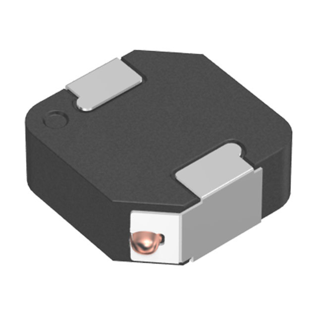
The SPM10040T-150M-HZ is a 15 µH shielded drum core wirewound inductor manufactured by TDK Corporation, rated for 6.8 A continuous current with a maximum DC resistance of 44.33mOhm. This component is designed for surface mount applications in automotive and industrial circuits requiring stable inductance performance across the -40°C to 125°C operating range.
The SPM10040T-150M-HZ carries a "Not For New Designs" status, indicating that TDK has transitioned this model out of active production. Identifying equivalent substitute parts is necessary to maintain design continuity, ensure supply chain reliability, and support existing applications requiring this inductance value and current rating.
Substiute Parts
Key Parameters
| Parameter | Value |
|---|---|
| Inductance | 15 µH |
| Current Rating | 6.8 A |
| DC Resistance (Max) | 44.33 mOhm |
| Saturation Current (Isat) | 4.8 A |
| Shielding | Shielded |
| Core Type | Metal |
| Tolerance | ±20% |
| Operating Temperature | -40°C ~ 125°C |
| Package | Nonstandard, Surface Mount |
| Mounting Type | Surface Mount |
| Size | 10.70mm L x 10.00mm W x 4.00mm H |
| Ratings | AEC-Q200 |
| RoHS Status | ROHS3 Compliant |
| MSL | 1 (Unlimited) |
Substitute Part Grouping Explanation
Substitution eligibility for the SPM10040T-150M-HZ is determined by the following critical parameters:
Primary Matching Criteria:
- Inductance value: 15 µH (exact match required)
- Tolerance: ±20% (must match or be tighter)
- Core material: Metal (shielded construction)
- Shielding: Shielded (electromagnetic containment requirement)
- Package dimensions: 10.70mm L x 10.00mm W x 4.00mm H (physical fit)
- Mounting type: Surface Mount (assembly compatibility)
- Operating temperature range: -40°C ~ 125°C (thermal envelope)
Secondary Compatibility Parameters:
- Current rating: Must support the application's maximum current demand
- DC resistance: Lower or equal values are acceptable; higher values increase power dissipation
- Saturation current: Must not fall below the circuit's peak current requirements
- AEC-Q200 certification: Maintained for automotive-grade reliability
The SPM10040T-150M-HZR qualifies as a direct substitute based on matching inductance, core type, shielding, package dimensions, temperature range, and AEC-Q200 certification. Differences in current rating and DC resistance are noted in the parameter comparison table below.
Parameter Comparison
| Parameter | SPM10040T-150M-HZ (Original) | SPM10040T-150M-HZR (Substitute) |
|---|---|---|
| Inductance | 15 µH | 15 µH |
| Tolerance | ±20% | ±20% |
| Current Rating (Amps) | 6.8 A | 5 A |
| Saturation Current (Isat) | 4.8 A | 4.7 A |
| DC Resistance (Max) | 44.33 mOhm | 49.5 mOhm |
| Shielding | Shielded | Shielded |
| Core Material | Metal | Metal |
| Operating Temperature | -40°C ~ 125°C | -40°C ~ 125°C |
| Package Dimensions | 10.70mm L x 10.00mm W x 4.00mm H | 10.70mm L x 10.00mm W x 4.00mm H |
| Mounting Type | Surface Mount | Surface Mount |
| AEC-Q200 Certification | Yes | Yes |
| RoHS Status | ROHS3 Compliant | ROHS3 Compliant |
| MSL | 1 (Unlimited) | 1 (Unlimited) |
| Product Status | Not For New Designs | Active |
Engineering Selection Recommendations
The SPM10040T-150M-HZR is the manufacturer-recommended substitute for the SPM10040T-150M-HZ. Both components maintain AEC-Q200 automotive-grade certification and ROHS3 compliance, ensuring regulatory and quality standards are preserved.
The substitute part differs in two electrical parameters: current rating (5 A versus 6.8 A) and DC resistance (49.5 mOhm versus 44.33 mOhm). Selection of the SPM10040T-150M-HZR is appropriate when the application's maximum continuous current does not exceed 5 A and the additional 5.17 mOhm DC resistance does not create unacceptable power dissipation or thermal constraints.
For applications requiring the full 6.8 A current rating or lower DC resistance of the original part, alternative inductors with matching inductance and current specifications must be evaluated. The substitute part's active product status provides improved long-term supply chain availability compared to the original "Not For New Designs" designation.
Frequently Asked Questions (FAQ)
Q: Can the SPM10040T-150M-HZR replace the SPM10040T-150M-HZ in all applications?
A: The SPM10040T-150M-HZR is a direct physical and electrical substitute for applications where the maximum continuous current does not exceed 5 A. If your circuit requires the full 6.8 A rating of the original part, the substitute is not suitable without circuit redesign or thermal analysis to confirm the higher DC resistance is acceptable.
Q: What is the impact of the higher DC resistance in the substitute part?
A: The SPM10040T-150M-HZR has a maximum DC resistance of 49.5 mOhm compared to 44.33 mOhm in the original. This 5.17 mOhm increase results in higher resistive losses (I²R heating). For a 5 A circuit, this represents approximately 1.24 W additional dissipation. Verify that thermal management in your application can accommodate this increase.
Q: Are the physical dimensions identical between the two parts?
A: Yes. Both the SPM10040T-150M-HZ and SPM10040T-150M-HZR share identical package dimensions of 10.70mm length, 10.00mm width, and 4.00mm height. No PCB layout modifications are required for substitution.
Q: Do both parts meet automotive qualification standards?
A: Yes. Both components carry AEC-Q200 certification, confirming compliance with automotive-grade reliability and performance requirements. Both are ROHS3 compliant and have MSL rating of 1 (unlimited moisture sensitivity).
Q: Why is the original part marked "Not For New Designs"?
A: The "Not For New Designs" status indicates that TDK has discontinued active production and recommends the SPM10040T-150M-HZR for new circuit designs. This status does not affect the performance or reliability of existing inventory; it reflects the manufacturer's product lifecycle management strategy.
Q: What is the saturation current difference, and does it matter?
A: The original part has Isat of 4.8 A; the substitute has 4.7 A. Both values are very close and represent the current level at which inductance begins to degrade. For applications operating below 4.7 A, this difference is negligible. Verify your circuit's peak current does not exceed this threshold.
Alternative Parts

SJ6012L2TP
Littelfuse Inc.
6 Alternative Parts

JMK107BBJ476MA-RE
Taiyo Yuden
10 Alternative Parts

GMK107BBJ475MA-T
Taiyo Yuden
5 Alternative Parts
SJ6020N2ARP
Littelfuse Inc.
3 Alternative Parts
SJ6025R2ATP
Littelfuse Inc.
4 Alternative Parts

2474-05L
API Delevan Inc.
1 Alternative Parts

4590R-684K
API Delevan Inc.
1 Alternative Parts

CM6560R-334
API Delevan Inc.
1 Alternative Parts

CM6460-104
API Delevan Inc.
1 Alternative Parts

5526-12
API Delevan Inc.
1 Alternative Parts