


Request Quote
(Ships tomorrow)
SPD30N06S2L-13 N-Channel MOSFET Equivalent & Substitute Parts
Part Overview
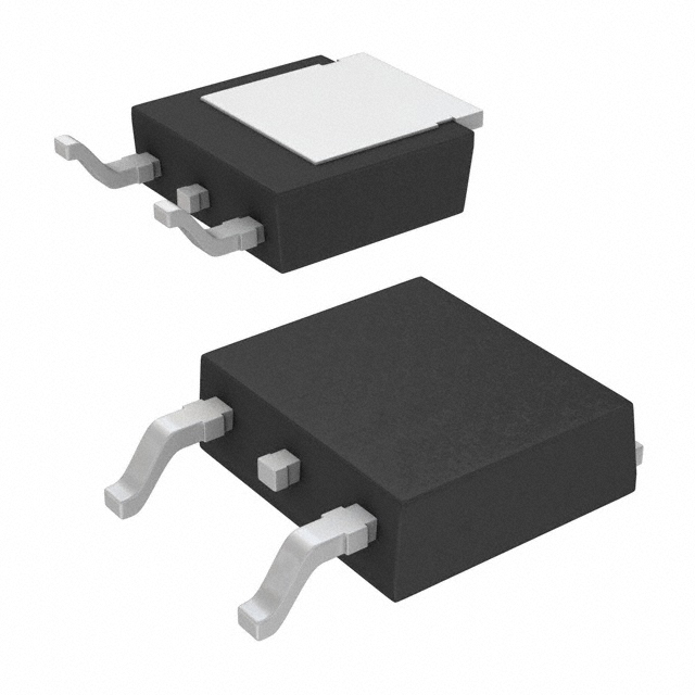
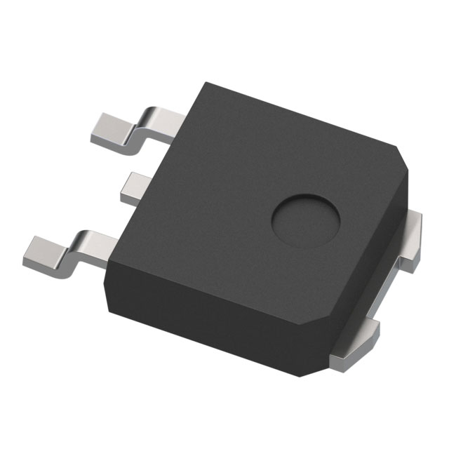
The SPD30N06S2L-13 is an N-Channel MOSFET manufactured by Infineon Technologies, rated for 55V drain-to-source voltage with 30A continuous drain current in a TO-252-3 (DPAK) surface mount package. This device is classified as obsolete, necessitating identification of functionally equivalent alternatives for ongoing production and maintenance applications. Substitute parts must maintain compatibility across voltage rating, current capacity, package type, and thermal characteristics to ensure direct replacement capability.
Substiute Parts
Key Parameters
| Parameter | SPD30N06S2L-13 | Unit |
|---|---|---|
| Drain-to-Source Voltage (Vdss) | 55 | V |
| Continuous Drain Current (Id) @ 25°C | 30 | A |
| On-State Resistance (Rds On) @ 30A, 10V | 13 | mOhm |
| Gate Threshold Voltage (Vgs(th)) @ 80µA | 2 | V |
| Gate Charge (Qg) @ 10V | 69 | nC |
| Power Dissipation (Max) | 136 | W |
| Operating Temperature Range | -55 to 175 | °C |
| Package Type | TO-252-3 (DPAK) | — |
| Product Status | Obsolete | — |
Substitute Part Grouping Explanation
Substitution logic for the SPD30N06S2L-13 is based on the following critical parameters:
Voltage Compatibility: All substitute parts must maintain a Vdss rating of 55V or higher to ensure safe operation within the original circuit voltage envelope.
Current Rating: Substitute parts must support a continuous drain current (Id) of 30A or greater at 25°C to handle the original design current load.
On-State Resistance (Rds On): The original part specifies 13 mOhm @ 30A, 10V. Substitute parts with comparable or lower Rds On values maintain thermal performance and power efficiency characteristics.
Package Compatibility: All substitutes must use the TO-252-3 (DPAK) surface mount package to ensure mechanical and electrical compatibility with existing PCB layouts.
Gate Charge (Qg): Gate charge affects switching speed and driver circuit requirements. Substitutes with similar Qg values (69 nC reference) minimize circuit redesign needs.
Thermal Rating: Power dissipation capability must be sufficient for the application thermal environment. The original 136W rating establishes the thermal performance baseline.
RoHS Compliance: Active and current-generation substitutes prioritize RoHS3 compliance for regulatory alignment in new designs.
Parameter Comparison
| Parameter | SPD30N06S2L-13 | IRLR3915TRPBF | IRFR4105ZTRPBF | IRFR4105TRPBF | BUK7212-55B,118 | STD60NF55LT4 | STD60NF55LAT4 | TSM120N06LCP ROG | Unit |
|---|---|---|---|---|---|---|---|---|---|
| Vdss | 55 | 55 | 55 | 55 | 55 | 55 | 55 | 60 | V |
| Id @ 25°C | 30 | 30 | 30 | 27 | 75 | 60 | 60 | 70 | A |
| Rds On (Max) @ 10V | 13 | 14 | 24.5 | 45 | 12 | 15 | 15 | 12 | mOhm |
| Vgs(th) (Max) | 2 | 3 | 4 | 4 | 4 | 2 | 2 | 2.5 | V |
| Qg @ 10V | 69 | 92 | 27 | 34 | 35 | 56 | 40 | 37 | nC |
| Power Dissipation (Max) | 136 | 120 | 48 | 68 | 167 | 100 | 110 | 125 | W |
| Operating Temp Range | -55 to 175 | -55 to 175 | -55 to 175 | -55 to 175 | -55 to 185 | -55 to 175 | -55 to 175 | -55 to 150 | °C |
| Package | TO-252-3 | TO-252-3 | TO-252-3 | TO-252-3 | TO-252-3 | TO-252-3 | TO-252-3 | TO-252-3 | — |
| Product Status | Obsolete | Active | Not For New Designs | Active | Obsolete | Active | Active | Active | — |
| RoHS Status | Non-compliant | ROHS3 Compliant | ROHS3 Compliant | ROHS3 Compliant | ROHS3 Compliant | ROHS3 Compliant | ROHS3 Compliant | ROHS3 Compliant | — |
Engineering Selection Recommendations
Primary Substitute: IRLR3915TRPBF
The IRLR3915TRPBF is the closest functional equivalent to the SPD30N06S2L-13. It maintains identical voltage (55V) and current (30A) ratings with comparable on-state resistance (14 mOhm vs. 13 mOhm). The part is currently in active production status with ROHS3 compliance, making it suitable for new designs and ongoing production. Power dissipation (120W) is slightly lower than the original (136W) but remains adequate for most applications. The HEXFET® series technology provides proven reliability in industrial applications.
Secondary Substitute: STD60NF55LT4
The STD60NF55LT4 from STMicroelectronics offers higher current capacity (60A) and improved on-state resistance (15 mOhm) while maintaining the 55V voltage rating. This part is actively produced with ROHS3 compliance and AEC-Q101 automotive qualification. The increased current rating provides design margin for applications requiring higher transient current handling. The STripFET™ II technology delivers enhanced thermal performance (100W dissipation).
Tertiary Substitute: STD60NF55LAT4
The STD60NF55LAT4 provides similar electrical characteristics to the STD60NF55LT4 with SuperFET® II technology and AEC-Q101 automotive qualification. This part supports 60A continuous current with 15 mOhm on-state resistance. The higher power dissipation rating (110W) and automotive-grade qualification make it suitable for demanding thermal environments and regulated applications.
Higher Current Alternative: BUK7212-55B,118
The BUK7212-55B,118 from Nexperia is a high-current alternative rated for 75A continuous drain current with 12 mOhm on-state resistance. This part is suitable for applications requiring significant current headroom beyond the original 30A specification. Although classified as obsolete, it remains in inventory and offers superior thermal performance (167W). AEC-Q101 automotive qualification and extended temperature range (-55°C to 185°C) support demanding applications.
Voltage-Margin Alternative: TSM120N06LCP ROG
The TSM120N06LCP ROG from Taiwan Semiconductor Corporation provides a 60V voltage rating with 70A current capacity and 12 mOhm on-state resistance. This part is actively produced with ROHS3 compliance and offers higher voltage margin for circuits operating near the 55V limit. The 125W power dissipation and 4.5V/10V drive voltage compatibility support direct circuit integration.
Not Recommended: IRFR4105TRPBF and IRFR4105ZTRPBF
The IRFR4105TRPBF (27A, 45 mOhm) and IRFR4105ZTRPBF (30A, 24.5 mOhm) exhibit significantly higher on-state resistance compared to the original part, resulting in increased power dissipation and thermal stress. The IRFR4105ZTRPBF is classified as "Not For New Designs," limiting its applicability to legacy system maintenance only. These parts are suitable only for applications where the original 13 mOhm specification is not critical.
Frequently Asked Questions (FAQ)
Q: Can the IRLR3915TRPBF directly replace the SPD30N06S2L-13 without circuit modifications?
A: Yes. The IRLR3915TRPBF maintains identical voltage (55V) and current (30A) ratings with comparable on-state resistance (14 mOhm vs. 13 mOhm). The TO-252-3 package is mechanically and electrically identical. Gate charge (92 nC vs. 69 nC) is slightly higher but remains within typical gate driver capability ranges. No PCB layout changes are required.
Q: What is the primary difference between STD60NF55LT4 and STD60NF55LAT4?
A: Both parts share identical electrical specifications (55V, 60A, 15 mOhm). The STD60NF55LAT4 includes AEC-Q101 automotive qualification and is designated for automotive-grade applications. The STD60NF55LT4 is suitable for industrial and general-purpose applications. Selection depends on application regulatory requirements.
Q: Why does the TSM120N06LCP ROG have a 60V rating instead of 55V?
A: The TSM120N06LCP ROG is rated for 60V Vdss, providing additional voltage margin above the original 55V specification. This higher rating is compatible with 55V circuit designs and offers protection against voltage transients. The part is suitable for applications where voltage margin is beneficial.
Q: Is the BUK7212-55B,118 suitable for new production despite its obsolete status?
A: The BUK7212-55B,118 is classified as obsolete but remains in inventory (7,248 units available). It is suitable for legacy system maintenance and repair. For new production designs, active-status alternatives such as IRLR3915TRPBF or STD60NF55LT4 are recommended to ensure long-term supply continuity and design support.
Q: What is the significance of RoHS3 compliance in substitute selection?
A: RoHS3 compliance indicates conformance to current environmental and hazardous substance restrictions. All recommended active substitutes (IRLR3915TRPBF, STD60NF55LT4, STD60NF55LAT4, TSM120N06LCP ROG) carry ROHS3 certification, ensuring regulatory alignment for products sold in regulated markets. The original SPD30N06S2L-13 is RoHS non-compliant, making compliant substitutes necessary for new designs.
Q: How does gate charge (Qg) affect circuit performance during substitution?
A: Gate charge determines the energy required to switch the MOSFET on and off. The original part specifies 69 nC at 10V. The IRLR3915TRPBF (92 nC) requires slightly more gate charge, potentially increasing switching losses in high-frequency applications. The STD60NF55LT4 (56 nC) and TSM120N06LCP ROG (37 nC) require less gate charge, improving switching efficiency. Gate driver circuits must supply sufficient current to meet the specified gate charge within the required switching time.
Q: Are all substitute parts available in the same packaging options as the original?
A: All recommended substitutes use the TO-252-3 (DPAK) surface mount package, identical to the original SPD30N06S2L-13. Packaging options vary by supplier: IRLR3915TRPBF is available in Cut Tape (CT) & Digi-Reel®; STD60NF55LT4 and STD60NF55LAT4 are available in Cut Tape (CT) & Digi-Reel®; TSM120N06LCP ROG is available in Tape & Reel (TR). Verify packaging availability with your supplier for production requirements.
Q: What thermal considerations apply when substituting to higher-current parts like BUK7212-55B,118 or STD60NF55LAT4?
A: Higher-current parts (60A to 75A) offer increased power dissipation capability (100W to 167W) compared to the original (136W). These parts are suitable for applications requiring thermal margin or higher transient current handling. PCB thermal design (copper area, via placement, thermal vias) must accommodate the selected part's power dissipation characteristics. Consult device datasheets for thermal resistance (θJA) specifications and thermal management recommendations.
Alternative Parts

SJ6012L2TP
Littelfuse Inc.
6 Alternative Parts

JMK107BBJ476MA-RE
Taiyo Yuden
10 Alternative Parts

GMK107BBJ475MA-T
Taiyo Yuden
5 Alternative Parts
SJ6020N2ARP
Littelfuse Inc.
3 Alternative Parts
SJ6025R2ATP
Littelfuse Inc.
4 Alternative Parts

2474-05L
API Delevan Inc.
1 Alternative Parts

4590R-684K
API Delevan Inc.
1 Alternative Parts

CM6560R-334
API Delevan Inc.
1 Alternative Parts

CM6460-104
API Delevan Inc.
1 Alternative Parts

5526-12
API Delevan Inc.
1 Alternative Parts