


Request Quote
(Ships tomorrow)
SPD07N20 N-Channel MOSFET 200V 7A Equivalent & Substitute Parts
Part Overview
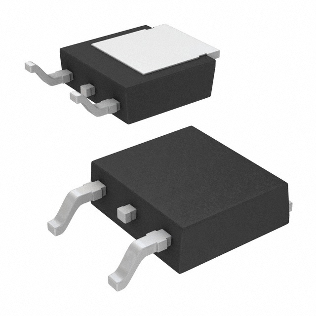
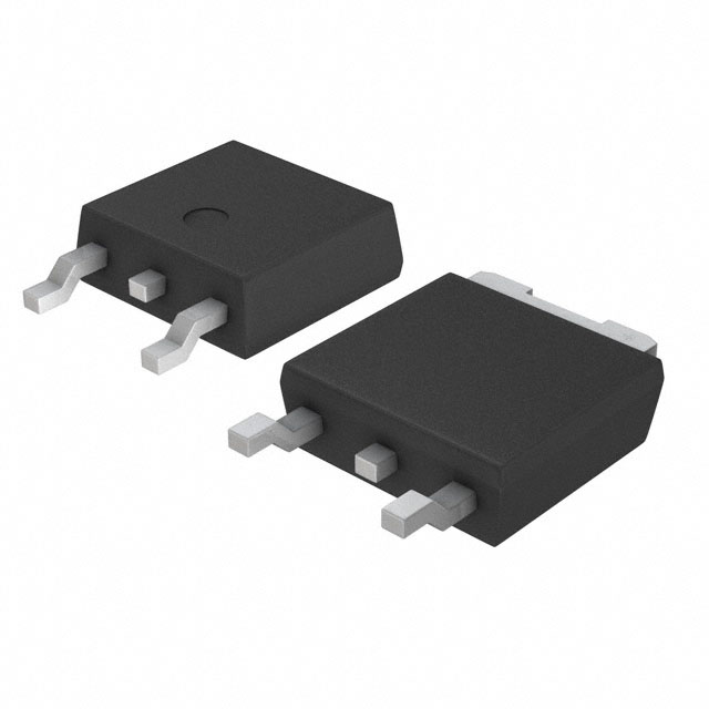
The SPD07N20 is an N-Channel MOSFET manufactured by Infineon Technologies, rated for 200V drain-to-source voltage and 7A continuous drain current in a TO-252-3 (DPAK) surface mount package. This device is part of the SIPMOS® series and is designed for general-purpose switching applications requiring moderate current handling at elevated voltages.
The SPD07N20 is discontinued at DiGi Electronics, necessitating identification of functionally equivalent alternatives. Substitute parts must maintain compatibility with existing PCB layouts, thermal management requirements, and electrical performance specifications within acceptable operating parameters.
Substiute Parts
Key Parameters
| Parameter | SPD07N20 Value | Unit |
|---|---|---|
| Drain-to-Source Voltage (Vdss) | 200 | V |
| Continuous Drain Current (Id) @ 25°C | 7 | A |
| On-State Resistance (Rds On) @ 4.5A, 10V | 400 | mOhm |
| Gate Threshold Voltage (Vgs(th)) @ 1mA | 4 | V |
| Gate Charge (Qg) @ 10V | 31.5 | nC |
| Input Capacitance (Ciss) @ 25V | 530 | pF |
| Power Dissipation (Max) | 40 | W |
| Operating Temperature Range | -55 to 175 | °C |
| Package Type | TO-252-3 (DPAK) | — |
| Mounting Type | Surface Mount | — |
Substitute Part Grouping Explanation
Substitution of the SPD07N20 is determined by the following critical electrical and mechanical parameters:
Voltage Rating: All substitute parts must maintain a minimum Vdss of 200V to ensure safe operation in the original application circuit.
Current Rating: The SPD07N20 specifies 7A continuous drain current. Substitute parts with lower current ratings (5A or 4.8A) are acceptable only when the application circuit does not require the full 7A specification. Parts with equal or higher current ratings provide direct substitution capability.
Package Compatibility: All substitute parts must use the TO-252-3 (DPAK) surface mount package to ensure PCB footprint compatibility without layout modifications.
On-State Resistance (Rds On): The SPD07N20 specifies 400 mOhm maximum at 4.5A and 10V gate drive. Substitute parts with higher Rds On values (600 mOhm or 800 mOhm) result in increased power dissipation and heat generation, requiring thermal design verification in the application circuit.
Gate Charge (Qg): The SPD07N20 specifies 31.5 nC at 10V. Substitute parts with lower gate charge values reduce driver circuit stress and switching losses.
Temperature Range: The SPD07N20 operates from -55°C to 175°C. Substitute parts with reduced upper temperature limits (150°C) have restricted operating range.
Compliance Status: RoHS3 compliance is maintained across all substitute parts. REACH status varies and must be evaluated for regulatory requirements in the target application region.
Parameter Comparison
| Parameter | SPD07N20 | IRFR220NTRLPBF | IRFR220NTRPBF | IRFR220PBF | IRFR220TRLPBF | IRFR220TRPBF |
|---|---|---|---|---|---|---|
| Manufacturer | Infineon | Infineon | Infineon | Vishay Siliconix | Vishay Siliconix | Vishay Siliconix |
| Vdss (V) | 200 | 200 | 200 | 200 | 200 | 200 |
| Id @ 25°C (A) | 7 | 5 | 5 | 4.8 | 4.8 | 4.8 |
| Rds On @ 10V (mOhm) | 400 @ 4.5A | 600 @ 2.9A | 600 @ 2.9A | 800 @ 2.9A | 800 @ 2.9A | 800 @ 2.9A |
| Vgs(th) (V) | 4 @ 1mA | 4 @ 250µA | 4 @ 250µA | 4 @ 250µA | 4 @ 250µA | 4 @ 250µA |
| Qg @ 10V (nC) | 31.5 | 23 | 23 | 14 | 14 | 14 |
| Ciss @ 25V (pF) | 530 | 300 | 300 | 260 | 260 | 260 |
| Power Dissipation (W) | 40 | 43 | 43 | 42 | 42 | 42 |
| Operating Temperature (°C) | -55 to 175 | -55 to 175 | -55 to 175 | -55 to 150 | -55 to 150 | -55 to 150 |
| Package | TO-252-3 | TO-252-3 | TO-252-3 | TO-252-3 | TO-252-3 | TO-252-3 |
| Product Status | Discontinued | Not For New Designs | Active | Active | Active | Active |
| RoHS3 Compliance | Yes | Yes | Yes | Yes | Yes | Yes |
Engineering Selection Recommendations
Primary Substitute: IRFR220NTRPBF
The IRFR220NTRPBF is the recommended substitute for new designs and production applications. This part is manufactured by Infineon Technologies with Active product status, ensuring long-term availability and supply chain stability. It maintains the 200V voltage rating and TO-252-3 package compatibility. The 5A continuous drain current is lower than the SPD07N20's 7A specification; however, this part is suitable for applications where the circuit design does not require the full 7A capability. The operating temperature range extends to 175°C, matching the SPD07N20. RoHS3 compliance is confirmed.
Secondary Substitute: IRFR220TRPBF
The IRFR220TRPBF is manufactured by Vishay Siliconix and maintains Active product status. This part provides the same 200V voltage rating and TO-252-3 package compatibility. The 4.8A continuous drain current and 800 mOhm on-state resistance result in higher power dissipation compared to the SPD07N20. The operating temperature range is limited to 150°C, which restricts use in applications requiring the full -55°C to 175°C range. This part is suitable for applications with moderate current requirements and standard temperature operating conditions. RoHS3 compliance is confirmed; REACH status is affected.
Alternative Substitute: IRFR220TRLPBF
The IRFR220TRLPBF is manufactured by Vishay Siliconix with Active product status. Electrical specifications are identical to the IRFR220TRPBF, with 4.8A continuous drain current and 800 mOhm on-state resistance. The operating temperature range is limited to 150°C. This part differs only in packaging format (Tape & Reel) and REACH status (Vendor Undefined). Selection between IRFR220TRPBF and IRFR220TRLPBF depends on procurement requirements and supply chain considerations.
Not Recommended for New Designs: IRFR220NTRLPBF
The IRFR220NTRLPBF carries a "Not For New Designs" product status designation, indicating that the manufacturer does not recommend this part for new circuit development. Although it maintains 200V voltage rating and TO-252-3 package compatibility, the discontinued status trajectory makes it unsuitable for long-term production applications.
Not Recommended: IRFR220PBF
The IRFR220PBF is manufactured by Vishay Siliconix with Active status but has a reduced operating temperature range of -55°C to 150°C. This limitation excludes it from applications requiring the full SPD07N20 temperature specification. Additionally, REACH status is affected, requiring compliance verification for regulated markets.
Frequently Asked Questions (FAQ)
Q: Can the IRFR220NTRPBF directly replace the SPD07N20 in my circuit?
A: The IRFR220NTRPBF provides direct PCB footprint compatibility due to identical TO-252-3 packaging. Electrical compatibility depends on your circuit's current requirements. The IRFR220NTRPBF is rated for 5A continuous drain current compared to the SPD07N20's 7A. If your application circuit operates at or below 5A, direct substitution is valid. If your circuit requires the full 7A capability, the lower current rating of the IRFR220NTRPBF may result in thermal stress or circuit malfunction.
Q: What is the impact of higher on-state resistance in substitute parts?
A: The SPD07N20 specifies 400 mOhm on-state resistance at 4.5A and 10V gate drive. Substitute parts such as IRFR220TRPBF and IRFR220TRLPBF specify 800 mOhm at 2.9A and 10V gate drive. Higher on-state resistance increases power dissipation according to the relationship P = I²R. In a circuit operating at 5A, the SPD07N20 dissipates approximately 10W (5² × 0.4 = 10W), while the IRFR220TRPBF dissipates approximately 20W (5² × 0.8 = 20W). This doubling of power dissipation requires verification that the PCB thermal design and heat sinking are adequate for the substitute part.
Q: Are all substitute parts RoHS3 compliant?
A: Yes, all substitute parts listed in this reference maintain RoHS3 compliance. However, REACH status varies. IRFR220NTRLPBF and IRFR220TRPBF are REACH Affected, while IRFR220NTRPBF is REACH Unaffected. IRFR220TRLPBF has Vendor Undefined REACH status. Compliance requirements depend on the target market and application region. Verify REACH status with your procurement department if your application is subject to European Union regulations.
Q: What is the significance of gate charge differences between parts?
A: The SPD07N20 specifies 31.5 nC gate charge at 10V, while substitute parts specify 14 to 23 nC. Gate charge determines the energy required to switch the MOSFET on and off. Lower gate charge reduces driver circuit stress and switching losses. Substitute parts with lower gate charge values (14 nC for IRFR220PBF and IRFR220TRLPBF) provide improved switching efficiency. However, if your circuit uses a dedicated gate driver with sufficient current capability, gate charge differences have minimal impact on circuit performance.
Q: Can I use IRFR220PBF if my application operates below 150°C?
A: The IRFR220PBF is suitable for applications where the maximum junction temperature does not exceed 150°C. The SPD07N20 specifies an operating range of -55°C to 175°C, while IRFR220PBF is limited to -55°C to 150°C. If your thermal design ensures that the junction temperature remains below 150°C under all operating conditions (including worst-case ambient temperature and power dissipation), the IRFR220PBF is electrically compatible. However, this reduced temperature margin provides less safety headroom compared to the SPD07N20 or IRFR220NTRPBF.
Q: Why is IRFR220NTRPBF recommended over other IRFR220 variants?
A: The IRFR220NTRPBF is recommended because it maintains Active product status, ensuring continued availability and supply chain support. It is manufactured by Infineon Technologies, the same manufacturer as the SPD07N20, providing design continuity. The operating temperature range extends to 175°C, matching the SPD07N20 specification. While the 5A current rating is lower than the SPD07N20's 7A, this part is suitable for applications where circuit design does not require the full 7A capability. IRFR220NTRLPBF carries "Not For New Designs" status, making it unsuitable for long-term production. Vishay Siliconix variants (IRFR220TRPBF, IRFR220TRLPBF, IRFR220PBF) have reduced temperature ranges or affected REACH status, introducing additional compliance considerations.
Q: What packaging formats are available for substitute parts?
A: Substitute parts are available in multiple packaging formats: Cut Tape (CT) & Digi-Reel® for IRFR220NTRLPBF and IRFR220TRPBF, Tape & Reel (TR) for IRFR220TRLPBF, and Tube for IRFR220PBF. All parts use the same TO-252-3 (DPAK) surface mount package, ensuring PCB footprint compatibility. Packaging format selection depends on procurement volume and assembly line requirements. Cut Tape and Digi-Reel formats are suitable for moderate-volume production, while Tape & Reel is optimized for high-volume automated assembly. Tube packaging is typically used for lower-volume or manual assembly applications.
Alternative Parts

SJ6012L2TP
Littelfuse Inc.
6 Alternative Parts

JMK107BBJ476MA-RE
Taiyo Yuden
10 Alternative Parts

GMK107BBJ475MA-T
Taiyo Yuden
5 Alternative Parts
SJ6020N2ARP
Littelfuse Inc.
3 Alternative Parts
SJ6025R2ATP
Littelfuse Inc.
4 Alternative Parts

2474-05L
API Delevan Inc.
1 Alternative Parts

4590R-684K
API Delevan Inc.
1 Alternative Parts

CM6560R-334
API Delevan Inc.
1 Alternative Parts

CM6460-104
API Delevan Inc.
1 Alternative Parts

5526-12
API Delevan Inc.
1 Alternative Parts