


Request Quote
(Ships tomorrow)
SPB80N10L N-Channel 100V 80A MOSFET Equivalent & Substitute Parts
Part Overview
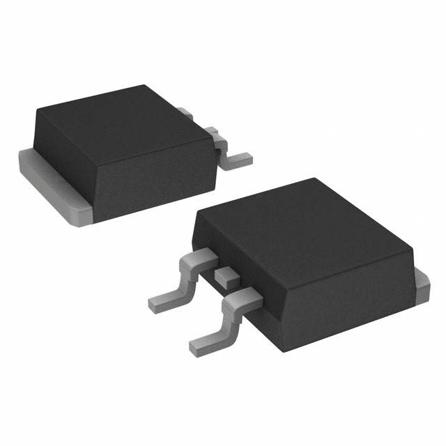
The SPB80N10L is an N-Channel MOSFET manufactured by Infineon Technologies, rated for 100V drain-to-source voltage and 80A continuous drain current at 25°C. The device is housed in a TO-263-3 (D2PAK) surface mount package with a maximum power dissipation of 250W. This part is classified as obsolete, making identification of functionally equivalent active alternatives necessary for ongoing design support and procurement.
Substiute Parts
Key Parameters
| Parameter | Value | Unit |
|---|---|---|
| Drain-to-Source Voltage (Vdss) | 100 | V |
| Continuous Drain Current (Id) @ 25°C | 80 | A |
| On-State Resistance (Rds On) @ 10V | 14 | mOhm |
| Gate Threshold Voltage (Vgs(th)) | 2 | V @ 2mA |
| Gate Charge (Qg) @ 10V | 240 | nC |
| Input Capacitance (Ciss) @ 25V | 4540 | pF |
| Power Dissipation (Max) | 250 | W |
| Operating Temperature Range | -55 to 175 | °C |
| Package Type | TO-263-3 (D2PAK) | Surface Mount |
| Product Status | Obsolete | — |
Substitute Part Grouping Explanation
Substitution eligibility for the SPB80N10L is determined by the following critical parameters:
Primary Matching Criteria:
- Drain-to-Source Voltage (Vdss): 100V (exact match required)
- Continuous Drain Current (Id) @ 25°C: 80A minimum
- Package Type: TO-263-3 (D2PAK) surface mount
- Operating Temperature Range: -55°C to 175°C (minimum requirement)
Secondary Compatibility Factors:
- On-State Resistance (Rds On): Comparable performance at rated current
- Gate Charge (Qg): Lower values indicate faster switching
- Input Capacitance (Ciss): Affects gate drive requirements
- Power Dissipation: Thermal management capability
All substitute parts listed maintain the 100V Vdss rating and TO-263-3 package format. Drain current ratings range from 61A to 110A, accommodating applications where the SPB80N10L's 80A specification is required. On-state resistance values remain within acceptable engineering tolerances for equivalent thermal performance.
Parameter Comparison
| Parameter | SPB80N10L | IRF8010STRLPBF | IRFS4510TRLPBF | PSMN013-100BS,118 | PSMN015-100B,118 | STB80NF10T4 | STB120NF10T4 |
|---|---|---|---|---|---|---|---|
| Manufacturer | Infineon | Infineon | Infineon | Nexperia | Nexperia | STMicroelectronics | STMicroelectronics |
| Vdss (V) | 100 | 100 | 100 | 100 | 100 | 100 | 100 |
| Id @ 25°C (A) | 80 | 80 | 61 | 68 | 75 | 80 | 110 |
| Rds On @ 10V (mOhm) | 14 | 15 | 13.9 | 13.9 | 15 | 15 | 10.5 |
| Vgs(th) (V) | 2 @ 2mA | 4 @ 250µA | 4 @ 100µA | 4 @ 1mA | 4 @ 1mA | 4 @ 250µA | 4 @ 250µA |
| Qg @ 10V (nC) | 240 | 120 | 87 | 59 | 90 | 182 | 233 |
| Ciss @ 25V (pF) | 4540 | 3830 | 3180 | 3195 | 4900 | 5500 | 5200 |
| Power Dissipation (W) | 250 | 260 | 140 | 170 | 300 | 300 | 312 |
| Operating Temp (°C) | -55 to 175 | -55 to 175 | -55 to 175 | -55 to 175 | -55 to 175 | -55 to 175 | -55 to 175 |
| Package | TO-263-3 | D2PAK | PG-TO263-3 | D2PAK | D2PAK | D2PAK | D2PAK |
| Product Status | Obsolete | Active | Active | Active | Active | Active | Active |
| RoHS Compliance | Non-compliant | ROHS3 Compliant | ROHS3 Compliant | ROHS3 Compliant | ROHS3 Compliant | ROHS3 Compliant | ROHS3 Compliant |
Engineering Selection Recommendations
Primary Substitutes (Exact Current Rating Match):
IRF8010STRLPBF and STB80NF10T4 are direct functional equivalents, both rated for 80A continuous drain current at 25°C with 100V Vdss. IRF8010STRLPBF offers lower gate charge (120 nC) compared to the original part (240 nC), enabling faster switching characteristics. STB80NF10T4 provides higher power dissipation capability (300W vs. 250W) with comparable on-state resistance. Both devices are in active production status with ROHS3 compliance, addressing the obsolescence of the SPB80N10L.
Secondary Substitutes (Higher Current Rating):
STB120NF10T4 provides 110A continuous drain current with superior on-state resistance (10.5 mOhm) and higher power dissipation (312W). This device accommodates applications requiring headroom beyond the original 80A specification while maintaining the same voltage class and package format.
Alternative Substitutes (Reduced Current Rating):
IRFS4510TRLPBF (61A) and PSMN013-100BS,118 (68A) are suitable for applications where the full 80A capability is not required. PSMN013-100BS,118 exhibits the lowest gate charge (59 nC) among all listed substitutes, optimizing for high-frequency switching applications.
Compliance Consideration:
All active substitute parts carry ROHS3 compliance certification, whereas the SPB80N10L is RoHS non-compliant. Selection of any substitute part satisfies modern regulatory requirements for new designs and procurement.
Frequently Asked Questions (FAQ)
Q: Can IRF8010STRLPBF directly replace SPB80N10L in existing designs?
A: IRF8010STRLPBF is functionally equivalent with identical 100V Vdss and 80A Id ratings. The primary difference is lower gate charge (120 nC vs. 240 nC), which reduces switching losses and improves efficiency. Gate drive circuits designed for the original part will operate with IRF8010STRLPBF without modification. Both devices use TO-263-3 (D2PAK) packaging with identical pinout.
Q: What is the significance of gate charge (Qg) differences among substitutes?
A: Gate charge determines the energy required to switch the MOSFET on and off. Lower gate charge values (IRF8010STRLPBF at 120 nC, PSMN013-100BS,118 at 59 nC) reduce gate drive power consumption and enable higher switching frequencies. Higher gate charge values (STB120NF10T4 at 233 nC) require more robust gate drive circuits but may offer other performance advantages such as lower on-state resistance or higher current capability.
Q: Are all substitute parts available in the same package format?
A: All substitute parts use TO-263-3 (D2PAK) surface mount packaging with identical mechanical dimensions and pinout. IRFS4510TRLPBF is specified as PG-TO263-3, which is functionally equivalent to the D2PAK format. PCB layout modifications are not required when substituting between these parts.
Q: Why does STB120NF10T4 have higher current rating (110A) than the original part (80A)?
A: STB120NF10T4 represents an enhanced device within the same voltage class and package family. The higher current rating reflects improved semiconductor technology and thermal design. Applications requiring only 80A operation can safely use STB120NF10T4 without derating; the additional current capacity provides design margin and thermal headroom.
Q: What is the impact of on-state resistance (Rds On) variation on circuit performance?
A: On-state resistance directly affects conduction losses and heat dissipation. The SPB80N10L specifies 14 mOhm at 58A and 10V gate voltage. Substitute parts range from 10.5 mOhm (STB120NF10T4) to 15 mOhm (IRF8010STRLPBF, PSMN015-100B,118, STB80NF10T4). Lower resistance values reduce power dissipation and improve efficiency; higher values increase thermal load. Selection depends on thermal management capability and efficiency requirements of the application.
Q: Is RoHS compliance a mandatory consideration for substitution?
A: RoHS compliance is a regulatory requirement for products sold in the European Union and many other markets. All active substitute parts listed carry ROHS3 certification, whereas the SPB80N10L is RoHS non-compliant. New designs and procurement should prioritize compliant alternatives to ensure market access and regulatory conformance.
Q: Can IRFS4510TRLPBF (61A) be used in applications designed for 80A operation?
A: IRFS4510TRLPBF is suitable only for applications where the actual operating current does not exceed 61A. If the design requires the full 80A capability of the original part, IRFS4510TRLPBF will operate outside its rated specification and is not recommended. For applications with confirmed current requirements below 61A, IRFS4510TRLPBF offers advantages including lower gate charge and reduced input capacitance.
Q: What thermal considerations apply when selecting among substitute parts?
A: Power dissipation ratings vary from 140W (IRFS4510TRLPBF) to 312W (STB120NF10T4). The original SPB80N10L is rated for 250W. Selection should account for the thermal resistance of the PCB layout, heatsinking provisions, and ambient operating temperature. Devices with higher power dissipation ratings provide greater thermal margin in high-current or high-frequency applications.
Alternative Parts

SJ6012L2TP
Littelfuse Inc.
6 Alternative Parts

JMK107BBJ476MA-RE
Taiyo Yuden
10 Alternative Parts

GMK107BBJ475MA-T
Taiyo Yuden
5 Alternative Parts
SJ6020N2ARP
Littelfuse Inc.
3 Alternative Parts
SJ6025R2ATP
Littelfuse Inc.
4 Alternative Parts

2474-05L
API Delevan Inc.
1 Alternative Parts

4590R-684K
API Delevan Inc.
1 Alternative Parts

CM6560R-334
API Delevan Inc.
1 Alternative Parts

CM6460-104
API Delevan Inc.
1 Alternative Parts

5526-12
API Delevan Inc.
1 Alternative Parts