


Request Quote
(Ships tomorrow)
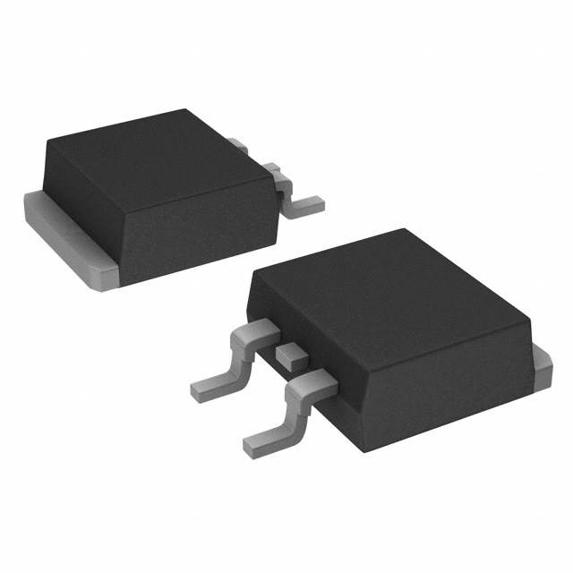
SPB47N10 N-Channel MOSFET 100V 47A Equivalent & Substitute Parts
Part Overview
The SPB47N10 is an N-Channel MOSFET manufactured by Infineon Technologies, rated for 100V drain-to-source voltage with 47A continuous drain current at 25°C. This device is housed in a PG-TO263-3-2 (D2PAK) surface mount package and is part of the SIPMOS® series. The SPB47N10 is classified as obsolete, making equivalent and substitute parts necessary for ongoing design support, production continuity, and component sourcing.
Substiute Parts
Key Parameters
| Parameter | Value | Unit |
|---|---|---|
| Drain-to-Source Voltage (Vdss) | 100 | V |
| Continuous Drain Current (Id) @ 25°C | 47 | A |
| On-State Resistance (Rds On) @ 33A, 10V | 33 | mOhm |
| Gate Threshold Voltage (Vgs(th)) @ 2mA | 4 | V |
| Gate Charge (Qg) @ 10V | 105 | nC |
| Power Dissipation (Max) | 175 | W |
| Operating Temperature Range | -55 to 175 | °C |
| Package Type | TO-263-3 (D2PAK) | - |
| Mounting Type | Surface Mount | - |
Substitute Part Grouping Explanation
Substitution of the SPB47N10 is determined by strict adherence to the following electrical and mechanical parameters:
Primary Substitution Criteria:
- Drain-to-Source Voltage (Vdss): Must equal 100V
- Continuous Drain Current (Id) @ 25°C: Must be ≥47A
- Package Type: Must be TO-263-3 (D2PAK) or equivalent surface mount configuration
- FET Type: Must be N-Channel MOSFET
- Operating Temperature Range: Must support -55°C to 175°C minimum
Secondary Compatibility Parameters:
- On-State Resistance (Rds On): Lower or equal values indicate improved performance
- Gate Charge (Qg): Lower values indicate faster switching characteristics
- Power Dissipation: Must support thermal requirements of the application
- RoHS Compliance: Preferred for modern manufacturing standards
All substitute parts listed meet or exceed the primary substitution criteria. Differences in secondary parameters reflect design variations across manufacturers and product series.
Parameter Comparison
| Parameter | SPB47N10 (Main) | PHB47NQ10T,118 | BUK7626-100B,118 | PSMN034-100BS,118 | STB40NF10LT4 |
|---|---|---|---|---|---|
| Manufacturer | Infineon | Nexperia | Nexperia | Nexperia | STMicroelectronics |
| Vdss (V) | 100 | 100 | 100 | 100 | 100 |
| Id @ 25°C (A) | 47 | 47 | 49 | 32 | 40 |
| Rds On (mOhm) | 33 @ 33A, 10V | 28 @ 25A, 10V | 26 @ 25A, 10V | 34.5 @ 15A, 10V | 33 @ 20A, 10V |
| Vgs(th) (V) | 4 @ 2mA | 4 @ 1mA | 4 @ 1mA | 4 @ 1mA | 2.5 @ 250µA |
| Qg @ 10V (nC) | 105 | 66 | 38 | 23.8 | 64 @ 4.5V |
| Power Dissipation (W) | 175 | 166 | 157 | 86 | 150 |
| Operating Temp (°C) | -55 to 175 | -55 to 175 | -55 to 175 | -55 to 175 | -65 to 175 |
| Package | TO-263-3 (D2PAK) | TO-263-3 (D2PAK) | TO-263-3 (D2PAK) | TO-263-3 (D2PAK) | TO-263-3 (D2PAK) |
| Product Status | Obsolete | Active | Obsolete | Active | Active |
| RoHS Status | Non-compliant | ROHS3 Compliant | ROHS3 Compliant | ROHS3 Compliant | ROHS3 Compliant |
Engineering Selection Recommendations
Primary Recommendation: PHB47NQ10T,118 (Nexperia)
The PHB47NQ10T,118 is the closest functional equivalent to the SPB47N10. It maintains identical voltage and current ratings (100V, 47A) with improved on-state resistance (28mOhm vs. 33mOhm) and significantly lower gate charge (66nC vs. 105nC). The device is Active status with ROHS3 compliance, ensuring long-term availability and regulatory compliance. Inventory availability is substantial (17,174 pcs). This part is suitable for direct replacement in most applications without circuit modification.
Secondary Recommendation: BUK7626-100B,118 (Nexperia)
The BUK7626-100B,118 offers slightly higher current capability (49A vs. 47A) with superior on-state resistance (26mOhm) and the lowest gate charge (38nC) among all substitutes. This device provides enhanced performance characteristics, particularly in switching speed and conduction losses. Although classified as Obsolete, it carries AEC-Q101 automotive qualification and ROHS3 compliance. Suitable for applications requiring improved thermal performance.
Tertiary Recommendation: STB40NF10LT4 (STMicroelectronics)
The STB40NF10LT4 is rated for 40A continuous drain current, which is below the SPB47N10 specification of 47A. This device is suitable only for applications where the actual current requirement does not exceed 40A. It offers Active product status, ROHS3 compliance, and an extended operating temperature range (-65°C to 175°C). The STripFET™ II series provides competitive on-state resistance (33mOhm) and moderate gate charge (64nC).
Not Recommended: PSMN034-100BS,118 (Nexperia)
The PSMN034-100BS,118 is rated for only 32A continuous drain current and 86W power dissipation, both significantly below the SPB47N10 specification. This device does not meet the primary substitution criteria and should not be used as a direct replacement for the SPB47N10.
Frequently Asked Questions (FAQ)
Q1: Can the PHB47NQ10T,118 be used as a direct replacement for the SPB47N10 without circuit modifications?
A: Yes. The PHB47NQ10T,118 maintains identical voltage (100V) and current (47A) ratings, operates across the same temperature range (-55°C to 175°C), and uses the same D2PAK package. The improved electrical characteristics (lower Rds On and Qg) represent performance enhancements rather than incompatibilities. No circuit modifications are required.
Q2: Why is the BUK7626-100B,118 classified as Obsolete if it is a suitable substitute?
A: Product status reflects manufacturer production and support status, not functional suitability. The BUK7626-100B,118 remains available in inventory (995 pcs) and carries AEC-Q101 automotive qualification. Obsolete status indicates that new production may be limited, but existing stock is suitable for applications. Verify long-term availability with your supplier before committing to high-volume designs.
Q3: What is the significance of the lower gate charge (Qg) in substitute parts?
A: Gate charge directly affects switching speed and driver circuit requirements. Lower Qg values (such as 38nC in BUK7626-100B,118 vs. 105nC in SPB47N10) result in faster switching transitions, reduced switching losses, and lower gate driver power consumption. This is a performance advantage in high-frequency switching applications.
Q4: Can the STB40NF10LT4 be used in applications designed for the SPB47N10?
A: Only if the actual circuit current requirement does not exceed 40A. The STB40NF10LT4 is rated for 40A continuous drain current, which is 7A below the SPB47N10 specification. Using this device in applications requiring 47A operation will result in thermal stress and potential device failure. Verify actual current requirements before substitution.
Q5: Why do substitute parts have different on-state resistance (Rds On) specifications measured at different current levels?
A: On-state resistance varies with gate-source voltage (Vgs) and drain current (Id). Manufacturers specify Rds On at different operating points based on typical application conditions. All listed substitutes are specified at 10V gate drive, which is the standard for the SPB47N10. Differences in measurement current (15A to 33A) reflect device design and characterization methodology. For direct comparison, refer to device datasheets for Rds On at identical operating conditions.
Q6: Are all substitute parts RoHS compliant?
A: The SPB47N10 is RoHS non-compliant. All recommended substitutes (PHB47NQ10T,118, BUK7626-100B,118, PSMN034-100BS,118, and STB40NF10LT4) are ROHS3 compliant. This compliance is advantageous for new designs and manufacturing processes subject to RoHS regulations.
Q7: What is the difference between the D2PAK and TO-263-3 package designations?
A: D2PAK and TO-263-3 are equivalent package designations for the same physical form factor: a surface mount package with two leads plus a tab for thermal connection. All listed parts use this identical package, ensuring mechanical and thermal compatibility.
Q8: How should I verify compatibility before implementing a substitute part?
A: Verify the following parameters match or exceed your application requirements: (1) Drain-to-Source Voltage ≥ 100V, (2) Continuous Drain Current ≥ 47A at 25°C, (3) Operating temperature range includes -55°C to 175°C, (4) Package is TO-263-3 (D2PAK). Consult device datasheets for detailed electrical characteristics and thermal performance curves specific to your operating conditions.
Alternative Parts

SJ6012L2TP
Littelfuse Inc.
6 Alternative Parts

JMK107BBJ476MA-RE
Taiyo Yuden
10 Alternative Parts

GMK107BBJ475MA-T
Taiyo Yuden
5 Alternative Parts
SJ6020N2ARP
Littelfuse Inc.
3 Alternative Parts
SJ6025R2ATP
Littelfuse Inc.
4 Alternative Parts

2474-05L
API Delevan Inc.
1 Alternative Parts

4590R-684K
API Delevan Inc.
1 Alternative Parts

CM6560R-334
API Delevan Inc.
1 Alternative Parts

CM6460-104
API Delevan Inc.
1 Alternative Parts

5526-12
API Delevan Inc.
1 Alternative Parts