


Request Quote
(Ships tomorrow)
Equivalent & Substitute Parts for SPB35N10 N-Channel MOSFET 100V 35A
Part Overview
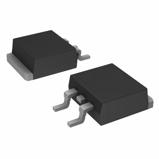
The SPB35N10 is an N-Channel MOSFET manufactured by Infineon Technologies, rated for 100V drain-to-source voltage with 35A continuous drain current at 25°C. The device is housed in a TO-263-3 (D2PAK) surface mount package and is rated for 150W power dissipation. The SPB35N10 is classified as obsolete, making identification of functionally equivalent substitute components necessary for ongoing design support and procurement.
Substitute parts must maintain electrical compatibility across critical parameters including voltage rating, current capacity, on-resistance characteristics, and thermal performance, while accommodating the same surface mount packaging standard.
Substiute Parts
Key Parameters
| Parameter | SPB35N10 | Unit |
|---|---|---|
| Drain-to-Source Voltage (Vdss) | 100 | V |
| Continuous Drain Current (Id) @ 25°C | 35 | A (Tc) |
| On-Resistance (Rds On) @ 26.4A, 10V | 44 | mOhm |
| Gate Threshold Voltage (Vgs(th)) @ 83µA | 4 | V |
| Gate Charge (Qg) @ 10V | 65 | nC |
| Power Dissipation (Max) | 150 | W (Tc) |
| Operating Temperature Range | -55 to 175 | °C (TJ) |
| Package Type | TO-263-3 (D2PAK) | Surface Mount |
| Product Status | Obsolete | — |
Substitute Part Grouping Explanation
Substitution eligibility for the SPB35N10 is determined by the following criteria:
Mandatory Electrical Parameters:
- Drain-to-Source Voltage (Vdss): 100V minimum
- Continuous Drain Current (Id): 35A or greater at 25°C
- On-Resistance (Rds On): Comparable or lower at rated conditions
- Gate Threshold Voltage (Vgs(th)): 4V nominal
- Operating Temperature Range: -55°C to 175°C minimum
Mandatory Mechanical Parameters:
- Package Type: TO-263-3 (D2PAK) surface mount configuration
- Lead configuration: 2 Leads + Tab
Compliance Considerations:
- RoHS compliance status (original part is non-compliant; active substitutes are RoHS3 compliant)
- Moisture Sensitivity Level: 1 (Unlimited)
The three substitute parts identified—FDB3682, FQB44N10TM, and STB30NF10T4—meet these criteria with variations in current capacity and power dissipation characteristics.
Parameter Comparison
| Parameter | SPB35N10 (Infineon) | FDB3682 (onsemi) | FQB44N10TM (onsemi) | STB30NF10T4 (STMicroelectronics) | Unit |
|---|---|---|---|---|---|
| Drain-to-Source Voltage (Vdss) | 100 | 100 | 100 | 100 | V |
| Continuous Drain Current (Id) @ 25°C | 35 (Tc) | 32 (Tc) | 43.5 (Tc) | 35 (Tc) | A |
| On-Resistance (Rds On) @ 10V | 44 @ 26.4A | 36 @ 32A | 39 @ 21.75A | 45 @ 15A | mOhm |
| Gate Threshold Voltage (Vgs(th)) | 4 @ 83µA | 4 @ 250µA | 4 @ 250µA | 4 @ 250µA | V |
| Gate Charge (Qg) @ 10V | 65 | 28 | 62 | 55 | nC |
| Power Dissipation (Max) | 150 (Tc) | 95 (Tc) | 146 (Tc) | 115 (Tc) | W |
| Operating Temperature Range | -55 to 175 | -55 to 175 | -55 to 175 | -55 to 175 | °C (TJ) |
| Package Type | TO-263-3 (D2PAK) | TO-263 (D2PAK) | TO-263 (D2PAK) | D2PAK | — |
| Product Status | Obsolete | Active | Active | Active | — |
| RoHS Status | Non-compliant | ROHS3 Compliant | ROHS3 Compliant | ROHS3 Compliant | — |
Engineering Selection Recommendations
STB30NF10T4 (STMicroelectronics)
The STB30NF10T4 provides the closest electrical match to the SPB35N10, with identical 100V voltage rating and 35A continuous drain current specification. On-resistance of 45mOhm at 10V is within acceptable tolerance of the original 44mOhm specification. Power dissipation rating of 115W is lower than the original 150W, requiring thermal design verification in high-power applications. The device is RoHS3 compliant and carries active product status, ensuring long-term availability and supply chain stability.
FQB44N10TM (onsemi)
The FQB44N10TM exceeds the original current specification at 43.5A continuous drain current, providing design margin for current-limited applications. On-resistance of 39mOhm at 10V is superior to the original specification. Power dissipation of 146W closely matches the original 150W rating. Gate charge of 62nC is comparable to the original 65nC. This device is suitable for applications requiring enhanced current capacity within the same voltage class. RoHS3 compliance and active status are confirmed.
FDB3682 (onsemi)
The FDB3682 operates at 100V with 32A continuous drain current, representing a 3A reduction from the original specification. On-resistance of 36mOhm at 10V is superior to the original 44mOhm. Gate charge of 28nC is significantly lower than the original 65nC, reducing switching losses. Power dissipation of 95W is substantially lower than the original 150W, limiting suitability to lower-power applications. This device is appropriate for designs where current requirements do not exceed 32A and thermal constraints are less demanding. RoHS3 compliance and active status are confirmed.
All three substitutes maintain the TO-263-3 (D2PAK) surface mount package configuration, ensuring mechanical compatibility with existing PCB layouts.
Frequently Asked Questions (FAQ)
Q: Can the FDB3682 be used as a direct replacement for the SPB35N10 in all applications?
A: The FDB3682 is electrically compatible at the 100V voltage rating and shares the same package type. However, the continuous drain current rating of 32A is 3A lower than the SPB35N10's 35A specification. Applications operating at or near 35A continuous current require verification that the FDB3682's 32A rating is sufficient. Power dissipation is also reduced to 95W, which may limit thermal performance in high-power designs.
Q: What is the primary advantage of the FQB44N10TM over the STB30NF10T4?
A: The FQB44N10TM provides higher continuous drain current at 43.5A compared to the STB30NF10T4's 35A, offering design margin for current-intensive applications. On-resistance is also lower at 39mOhm versus 45mOhm. Power dissipation of 146W is closer to the original 150W specification. The STB30NF10T4 provides a closer electrical match to the original SPB35N10 with identical current and voltage ratings.
Q: Are all substitute parts compatible with the original PCB layout?
A: Yes. All three substitute parts use the TO-263-3 (D2PAK) surface mount package with identical lead configuration (2 Leads + Tab). No PCB layout modifications are required for mechanical compatibility.
Q: What compliance advantage do the substitute parts offer over the original SPB35N10?
A: All three substitute parts are RoHS3 compliant, whereas the original SPB35N10 is RoHS non-compliant. This compliance status is mandatory for new designs targeting markets with RoHS regulatory requirements. All parts maintain Moisture Sensitivity Level 1 (Unlimited) and REACH Unaffected status.
Q: How do gate charge differences affect circuit performance?
A: Gate charge (Qg) determines the energy required to switch the MOSFET. The FDB3682 has significantly lower gate charge at 28nC compared to the original 65nC, reducing switching losses and driver power requirements. The FQB44N10TM at 62nC and STB30NF10T4 at 55nC are comparable to the original specification. Lower gate charge is advantageous in high-frequency switching applications.
Q: Which substitute is recommended for new designs?
A: Selection depends on application requirements. For current-matched performance, the STB30NF10T4 is recommended. For enhanced current capacity, the FQB44N10TM is appropriate. For lower-power applications with reduced thermal requirements, the FDB3682 is suitable. All three parts are active products with confirmed RoHS3 compliance and long-term availability.
Alternative Parts

SJ6012L2TP
Littelfuse Inc.
6 Alternative Parts

JMK107BBJ476MA-RE
Taiyo Yuden
10 Alternative Parts

GMK107BBJ475MA-T
Taiyo Yuden
5 Alternative Parts
SJ6020N2ARP
Littelfuse Inc.
3 Alternative Parts
SJ6025R2ATP
Littelfuse Inc.
4 Alternative Parts

2474-05L
API Delevan Inc.
1 Alternative Parts

4590R-684K
API Delevan Inc.
1 Alternative Parts

CM6560R-334
API Delevan Inc.
1 Alternative Parts

CM6460-104
API Delevan Inc.
1 Alternative Parts

5526-12
API Delevan Inc.
1 Alternative Parts