


Request Quote
(Ships tomorrow)
SM1615CE3/TR13 Equivalent & Substitute Parts
Part Overview
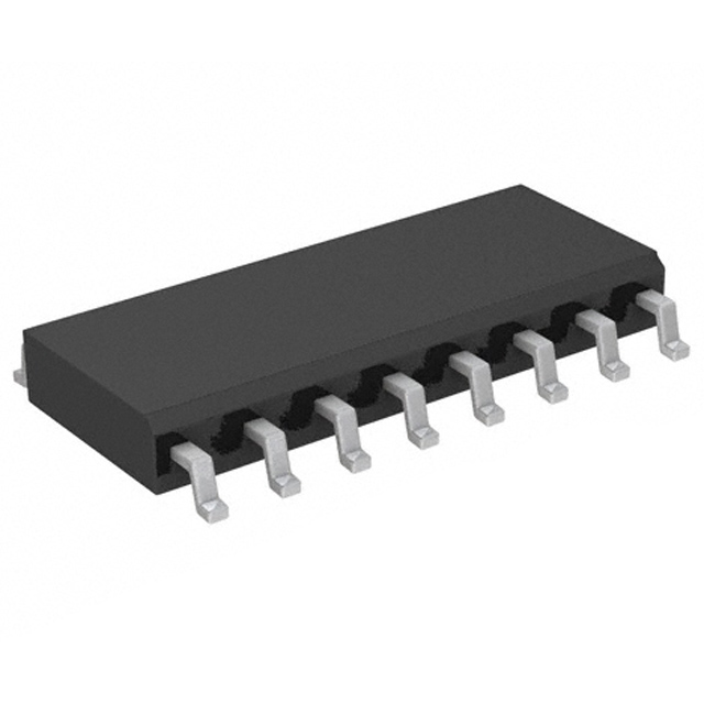
The SM1615CE3/TR13 is an active Transient Voltage Suppressor (TVS) diode manufactured by Microchip Technology, designed for general-purpose overvoltage protection applications. This bidirectional 8-channel Zener TVS diode operates with a 15V reverse standoff voltage and provides 30V clamping at peak pulse current. The device is packaged in a 16-SOIC surface mount configuration and is RoHS3 compliant with unlimited moisture sensitivity rating.
Equivalent and substitute parts are identified to support component availability, supply chain continuity, and design flexibility while maintaining electrical and mechanical compatibility within specified parameter tolerances.
Substiute Parts
Key Parameters
| Parameter | Value | Unit |
|---|---|---|
| Voltage - Reverse Standoff (Typ) | 15 | V |
| Voltage - Breakdown (Min) | 16.7 | V |
| Voltage - Clamping (Max) @ Ipp | 30 | V |
| Current - Peak Pulse (8/20µs) | 5 | A |
| Power - Peak Pulse | 300 | W |
| Bidirectional Channels | 8 | — |
| Capacitance @ 1MHz | 200 | pF |
| Operating Temperature Range | -55 to 150 | °C |
| Package / Case | 16-SOIC (0.154", 3.90mm Width) | — |
| Mounting Type | Surface Mount | — |
| RoHS Status | RoHS3 Compliant | — |
Substitute Part Grouping Explanation
Substitute parts for the SM1615CE3/TR13 are classified based on electrical parameter compatibility and mechanical interchangeability. The substitution logic is structured as follows:
Direct Equivalent Classification: Parts classified as direct equivalents share identical or functionally equivalent electrical specifications across all critical parameters: reverse standoff voltage (15V), breakdown voltage (16.7V minimum), clamping voltage (30V maximum), peak pulse current (5A at 8/20µs), power dissipation (300W), bidirectional channel count (8), and package configuration (16-SOIC surface mount). These parts are pin-compatible and functionally interchangeable without circuit modification.
Similar Substitute Classification: Parts classified as similar substitutes maintain compatibility in core protection function and package form factor but exhibit variations in one or more electrical parameters. Specifically, these parts may differ in clamping voltage, peak pulse current rating, power dissipation, capacitance characteristics, or operating temperature range. Similar substitutes are suitable for applications where the specified parameter variations remain within system design tolerances.
Key Parameters Determining Substitution:
- Reverse standoff voltage (15V nominal)
- Package type and pin configuration (16-SOIC)
- Bidirectional channel architecture (8 channels)
- Surface mount mounting type
- Zener TVS diode classification
Parameter Comparison
| Parameter | SM1615CE3/TR13 | SM1615C/TR13 | LCDA15C-8.TBT |
|---|---|---|---|
| Manufacturer | Microchip Technology | Microchip Technology | Semtech |
| Voltage - Reverse Standoff (Typ) | 15V | 15V | 15V (Max) |
| Voltage - Breakdown (Min) | 16.7V | 16.7V | 16.7V |
| Voltage - Clamping (Max) @ Ipp | 30V | 30V | 33V |
| Current - Peak Pulse (8/20µs) | 5A | 5A | 15A |
| Power - Peak Pulse | 300W | 300W | 500W |
| Bidirectional Channels | 8 | 8 | 8 |
| Capacitance @ 1MHz | 200pF | 200pF | 8pF |
| Operating Temperature Range | -55°C to 150°C | -55°C to 150°C | -55°C to 125°C |
| Package / Case | 16-SOIC (0.154", 3.90mm Width) | 16-SOIC (0.154", 3.90mm Width) | 16-SOIC (0.154", 3.90mm Width) |
| Mounting Type | Surface Mount | Surface Mount | Surface Mount |
| Product Status | Active | Active | Active |
| RoHS Status | RoHS3 Compliant | RoHS non-compliant | RoHS3 Compliant |
| Moisture Sensitivity Level | 1 (Unlimited) | 1 (Unlimited) | 1 (Unlimited) |
Engineering Selection Recommendations
SM1615C/TR13 (Microchip Technology): This part is a direct electrical equivalent to the SM1615CE3/TR13, maintaining identical specifications across voltage, current, power, and capacitance parameters. Both devices share the same 16-SOIC package and operating temperature range. The SM1615C/TR13 is classified as a direct substitute with full functional interchangeability. However, this part is RoHS non-compliant, which may restrict its use in applications or markets requiring RoHS3 certification. Selection of this substitute is appropriate only when RoHS compliance is not a design requirement.
LCDA15C-8.TBT (Semtech): This part is classified as a similar substitute, offering enhanced electrical performance characteristics compared to the SM1615CE3/TR13. The LCDA15C-8.TBT provides higher peak pulse current (15A versus 5A), increased power dissipation (500W versus 300W), and marginally higher clamping voltage (33V versus 30V). The device maintains the same 15V reverse standoff voltage, 16-SOIC package configuration, and 8-channel bidirectional architecture. The LCDA15C-8.TBT exhibits significantly lower capacitance (8pF versus 200pF at 1MHz), which may be advantageous in high-frequency applications. The operating temperature range is reduced to -55°C to 125°C. This part is RoHS3 compliant. Selection of the LCDA15C-8.TBT is appropriate for applications requiring higher transient current handling or where lower capacitance is beneficial, provided the reduced upper operating temperature limit is acceptable.
Frequently Asked Questions (FAQ)
Q: Can SM1615C/TR13 be used as a direct replacement for SM1615CE3/TR13?
A: Yes, the SM1615C/TR13 is electrically and mechanically equivalent to the SM1615CE3/TR13. Both devices share identical voltage ratings, current specifications, power dissipation, and package configuration. The primary distinction is RoHS compliance status. The SM1615C/TR13 is RoHS non-compliant, whereas the SM1615CE3/TR13 is RoHS3 compliant. Direct substitution is feasible only when RoHS certification is not required.
Q: What are the key differences between SM1615CE3/TR13 and LCDA15C-8.TBT?
A: Both devices maintain the same 15V reverse standoff voltage, 16.7V minimum breakdown voltage, and 8-channel bidirectional configuration in a 16-SOIC package. The LCDA15C-8.TBT provides enhanced transient protection with 15A peak pulse current (versus 5A) and 500W power dissipation (versus 300W). The clamping voltage is slightly higher at 33V. The LCDA15C-8.TBT exhibits substantially lower capacitance (8pF versus 200pF), which reduces signal distortion in high-frequency circuits. The operating temperature range is -55°C to 125°C, compared to -55°C to 150°C for the SM1615CE3/TR13.
Q: Is the LCDA15C-8.TBT suitable for all applications using SM1615CE3/TR13?
A: The LCDA15C-8.TBT is suitable for most applications, with two considerations. First, the reduced upper operating temperature limit (125°C versus 150°C) must be verified against system thermal requirements. Second, the lower capacitance (8pF versus 200pF) may affect circuit behavior in applications sensitive to device capacitance. In high-frequency signal protection circuits, the lower capacitance of the LCDA15C-8.TBT is typically advantageous. The higher current and power ratings provide enhanced protection margin.
Q: Are all three parts pin-compatible?
A: Yes, all three parts (SM1615CE3/TR13, SM1615C/TR13, and LCDA15C-8.TBT) are pin-compatible. All devices are packaged in 16-SOIC (0.154", 3.90mm width) surface mount configuration with identical pinout and footprint requirements.
Q: Which substitute part should be selected for new designs?
A: For new designs, the LCDA15C-8.TBT is recommended when RoHS3 compliance is required and the reduced operating temperature range is acceptable. The enhanced current and power ratings provide additional design margin for transient protection. For designs requiring the full -55°C to 150°C operating range with RoHS3 compliance, the SM1615CE3/TR13 is the appropriate selection. The SM1615C/TR13 is suitable only for legacy designs or applications where RoHS compliance is not mandated.
Q: What is the significance of capacitance differences between these parts?
A: Capacitance at 1MHz is a critical parameter in high-frequency signal protection applications. The SM1615CE3/TR13 and SM1615C/TR13 exhibit 200pF capacitance, while the LCDA15C-8.TBT exhibits 8pF. Lower capacitance reduces signal distortion, insertion loss, and impedance mismatch in high-speed data lines. In low-frequency power protection applications, capacitance differences are typically insignificant. Selection between these parts should consider the operating frequency range of the protected circuit.
Alternative Parts

SJ6012L2TP
Littelfuse Inc.
6 Alternative Parts

JMK107BBJ476MA-RE
Taiyo Yuden
10 Alternative Parts

GMK107BBJ475MA-T
Taiyo Yuden
5 Alternative Parts
SJ6020N2ARP
Littelfuse Inc.
3 Alternative Parts
SJ6025R2ATP
Littelfuse Inc.
4 Alternative Parts

2474-05L
API Delevan Inc.
1 Alternative Parts

4590R-684K
API Delevan Inc.
1 Alternative Parts

CM6560R-334
API Delevan Inc.
1 Alternative Parts

CM6460-104
API Delevan Inc.
1 Alternative Parts

5526-12
API Delevan Inc.
1 Alternative Parts