


Request Quote
(Ships tomorrow)
SFSCE10M7WF03-R0 Equivalent & Substitute Parts
Part Overview
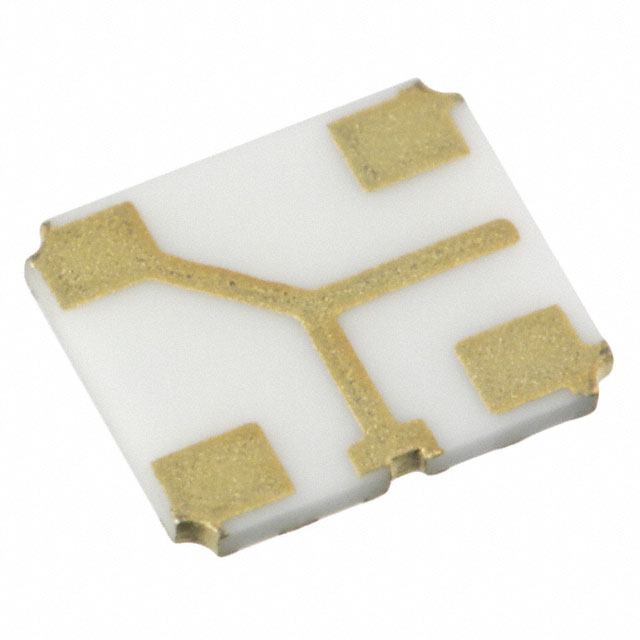
The SFSCE10M7WF03-R0 is a 10.7MHz center frequency FM ceramic filter manufactured by Murata Electronics, designed for surface mount applications with a 500 kHz bandwidth and 470 Ohm impedance. This part is classified as obsolete, making identification of suitable substitute components necessary for ongoing production and maintenance applications. The SFSCE series has been superseded by newer filter designs that maintain core electrical specifications while offering improved performance characteristics and active product status.
Substiute Parts
Key Parameters
| Parameter | Value |
|---|---|
| Center Frequency | 10.7 MHz |
| Bandwidth | 500 kHz |
| Impedance | 470 Ohm |
| Filter Type | FM |
| Insertion Loss | 6 dB |
| Mounting Type | Surface Mount |
| RoHS Status | ROHS3 Compliant |
| Moisture Sensitivity Level | 1 (Unlimited) |
Substitute Part Grouping Explanation
Substitution of the SFSCE10M7WF03-R0 is based on electrical parameter equivalence and compliance requirements. The primary substitute, SFECV10M7CQ0C01-R0, maintains identical electrical specifications across center frequency (10.7 MHz), bandwidth (500 kHz), impedance (470 Ohm), and filter type (FM). Both components are ROHS3 compliant and rated for EAR99 export classification.
The key parameters determining substitution eligibility are:
- Center frequency: 10.7 MHz (exact match required)
- Bandwidth: 500 kHz (exact match required)
- Impedance: 470 Ohm (exact match required)
- Filter type: FM (exact match required)
- Surface mount configuration (required for PCB compatibility)
- RoHS3 compliance (regulatory requirement)
Physical package differences exist between the main part and substitute, requiring PCB layout verification prior to implementation.
Parameter Comparison
| Parameter | SFSCE10M7WF03-R0 | SFECV10M7CQ0C01-R0 |
|---|---|---|
| Manufacturer | Murata Electronics | Murata Electronics |
| Center Frequency | 10.7 MHz | 10.7 MHz |
| Bandwidth | 500 kHz | 500 kHz |
| Impedance | 470 Ohm | 470 Ohm |
| Filter Type | FM | FM |
| Insertion Loss | 6 dB | 2 dB |
| Mounting Type | Surface Mount | Surface Mount |
| Package / Case | 1715 (4538 Metric), 4 PC Pad | 2706 (6915 Metric), 3 PC Pad |
| Size / Dimension | 0.177" L x 0.150" W (4.50mm x 3.80mm) | 0.272" L x 0.059" W (6.90mm x 1.50mm) |
| Height (Max) | 0.039" (1.00mm) | 0.067" (1.70mm) |
| Product Status | Obsolete | Active |
| RoHS Status | ROHS3 Compliant | ROHS3 Compliant |
| Moisture Sensitivity Level | 1 (Unlimited) | Not Applicable |
Engineering Selection Recommendations
The SFECV10M7CQ0C01-R0 is the manufacturer-recommended substitute for the obsolete SFSCE10M7WF03-R0. Both components maintain electrical equivalence across all critical FM filter parameters: 10.7 MHz center frequency, 500 kHz bandwidth, and 470 Ohm impedance. The substitute component offers improved insertion loss performance (2 dB versus 6 dB) and carries active product status with full ROHS3 compliance and REACH applicability.
Selection of the SFECV10M7CQ0C01-R0 requires PCB layout modification due to package differences. The substitute uses a 2706 (6915 Metric) package with 3 pads versus the original 1715 (4538 Metric) package with 4 pads. Physical dimensions differ significantly: the substitute is longer (0.272" versus 0.177") and narrower (0.059" versus 0.150"), with increased height (0.067" versus 0.039").
Frequently Asked Questions (FAQ)
Q: What electrical parameters must match for substitution of the SFSCE10M7WF03-R0?
A: Center frequency (10.7 MHz), bandwidth (500 kHz), impedance (470 Ohm), and filter type (FM) must remain identical. These parameters define the filter's functional role in FM receiver circuits and cannot be altered without circuit redesign.
Q: Why does the SFECV10M7CQ0C01-R0 have lower insertion loss than the original part?
A: Insertion loss is a performance characteristic determined by filter design and manufacturing process. The substitute represents a newer design iteration with improved signal transmission efficiency. Lower insertion loss reduces signal attenuation in the signal path.
Q: Can the SFECV10M7CQ0C01-R0 be used as a direct drop-in replacement?
A: No. While electrically equivalent, the substitute requires PCB layout modification. The package footprint differs in pad count (3 versus 4), physical dimensions, and height. PCB artwork must be updated to accommodate the 2706 package configuration.
Q: What is the significance of the different pad configurations?
A: The original SFSCE10M7WF03-R0 uses a 4-pad configuration in the 1715 package, while the SFECV10M7CQ0C01-R0 uses a 3-pad configuration in the 2706 package. Pad count and spacing determine solder joint formation and mechanical stability on the PCB. PCB design must match the selected component's pad layout.
Q: Are both components compliant with current regulatory requirements?
A: Yes. Both the SFSCE10M7WF03-R0 and SFECV10M7CQ0C01-R0 are ROHS3 compliant. The substitute additionally carries REACH applicability status, indicating compliance with European chemical substance regulations.
Q: What is the moisture sensitivity difference between these components?
A: The SFSCE10M7WF03-R0 carries MSL 1 (Unlimited), indicating no moisture sensitivity restrictions. The SFECV10M7CQ0C01-R0 lists MSL as Not Applicable, reflecting its ceramic filter construction with inherent moisture resistance. Both components are suitable for standard manufacturing and storage environments.
Alternative Parts

SJ6012L2TP
Littelfuse Inc.
6 Alternative Parts

JMK107BBJ476MA-RE
Taiyo Yuden
10 Alternative Parts

GMK107BBJ475MA-T
Taiyo Yuden
5 Alternative Parts
SJ6020N2ARP
Littelfuse Inc.
3 Alternative Parts
SJ6025R2ATP
Littelfuse Inc.
4 Alternative Parts

2474-05L
API Delevan Inc.
1 Alternative Parts

4590R-684K
API Delevan Inc.
1 Alternative Parts

CM6560R-334
API Delevan Inc.
1 Alternative Parts

CM6460-104
API Delevan Inc.
1 Alternative Parts

5526-12
API Delevan Inc.
1 Alternative Parts