


Request Quote
(Ships tomorrow)
SF2006G Equivalent & Substitute Parts
Part Overview
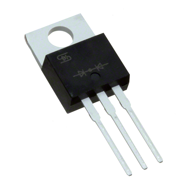
The SF2006G is a general-purpose rectifier diode manufactured by Taiwan Semiconductor Corporation, rated for 400 V DC reverse voltage and 20 A average rectified current in a Through Hole TO-220AB package. This component is classified as Active product status with RoHS3 compliance and unlimited moisture sensitivity level (MSL 1). Substitute parts are identified when equivalent electrical performance and mechanical compatibility are required for circuit design flexibility, inventory management, or supply chain continuity.
Substiute Parts
Key Parameters
| Parameter | Value | Unit |
|---|---|---|
| Voltage - DC Reverse (Vr) (Max) | 400 | V |
| Current - Average Rectified (Io) | 20 | A |
| Voltage - Forward (Vf) (Max) @ If | 1.3 V @ 10 A | V |
| Reverse Recovery Time (trr) | 35 | ns |
| Current - Reverse Leakage @ Vr | 5 | µA @ 400 V |
| Speed Classification | Fast Recovery ≤ 500ns, > 200mA (Io) | — |
| Mounting Type | Through Hole | — |
| Package / Case | TO-220-3 | — |
| Operating Temperature - Junction | -55°C ~ 150°C | — |
| RoHS Status | ROHS3 Compliant | — |
Substitute Part Grouping Explanation
Substitute parts for the SF2006G are identified based on the following critical parameters:
Voltage Rating Compatibility: All substitute parts must maintain a DC reverse voltage (Vr) rating of 400 V or higher to ensure safe operation in the same circuit topology.
Package Compatibility: All substitute parts must use the TO-220-3 package with Through Hole mounting to ensure mechanical fit and thermal management equivalence.
Speed Classification: All substitute parts must meet or exceed the Fast Recovery classification (≤ 500ns, > 200mA) to maintain switching performance characteristics.
Compliance Requirements: All substitute parts must maintain RoHS3 compliance and EAR99 export classification to satisfy regulatory and supply chain requirements.
Current Rating Consideration: While the SF2006G is rated for 20 A average rectified current, substitute parts with lower current ratings (such as 4 A per diode in array configurations) may be applied in circuits where the actual operating current does not exceed the substitute part's rating. Array configurations with multiple diodes in parallel or series-parallel arrangements can achieve equivalent current handling.
Parameter Comparison
| Parameter | SF2006G (Main Part) | SDUR2040CT | MURH840CTG |
|---|---|---|---|
| Manufacturer | Taiwan Semiconductor Corporation | SMC Diode Solutions | onsemi |
| Voltage - DC Reverse (Vr) (Max) | 400 V | 400 V | 400 V |
| Current - Average Rectified (Io) | 20 A | Not Specified | 4 A (per Diode) |
| Voltage - Forward (Vf) (Max) @ If | 1.3 V @ 10 A | 1.3 V @ 10 A | 2.2 V @ 4 A |
| Reverse Recovery Time (trr) | 35 ns | 45 ns | 28 ns |
| Current - Reverse Leakage @ Vr | 5 µA @ 400 V | 10 µA @ 400 V | 10 µA @ 400 V |
| Speed Classification | Fast Recovery ≤ 500ns, > 200mA | Fast Recovery ≤ 500ns, > 200mA | Fast Recovery ≤ 500ns, > 200mA |
| Package / Case | TO-220-3 | TO-220-3 | TO-220-3 |
| Operating Temperature - Junction | -55°C ~ 150°C | -55°C ~ 150°C | -65°C ~ 175°C |
| RoHS Status | ROHS3 Compliant | ROHS3 Compliant | ROHS3 Compliant |
| REACH Status | REACH Unaffected | REACH Affected | REACH Unaffected |
Engineering Selection Recommendations
SDUR2040CT (SMC Diode Solutions): This substitute part maintains identical voltage rating (400 V), forward voltage characteristics (1.3 V @ 10 A), and operating temperature range (-55°C ~ 150°C) as the SF2006G. Both parts are RoHS3 compliant with unlimited moisture sensitivity level (MSL 1). The SDUR2040CT is configured as a 1 Pair Common Cathode diode array in TO-220-3 package. Note that REACH Status is listed as Affected for this part, requiring verification of supply chain documentation. Reverse recovery time is slightly longer (45 ns versus 35 ns), remaining within fast recovery classification.
MURH840CTG (onsemi): This substitute part maintains the 400 V voltage rating and fast recovery speed classification. The MURH840CTG is part of the MEGAHERTZ™ series and offers an extended operating temperature range (-65°C ~ 175°C) compared to the SF2006G. This part is configured as a 1 Pair Common Cathode diode array with 4 A per diode rating. RoHS3 compliance and REACH Unaffected status are confirmed. Forward voltage is higher (2.2 V @ 4 A) and reverse recovery time is faster (28 ns). Current rating per diode is lower (4 A), requiring circuit design consideration for parallel or series-parallel configurations if full 20 A capacity is required.
Both substitute parts are Active product status with confirmed inventory availability and meet the mandatory mechanical and electrical compatibility criteria for TO-220-3 Through Hole applications at 400 V operation.
Frequently Asked Questions (FAQ)
Q: Can SDUR2040CT or MURH840CTG be used as direct 1:1 replacements for SF2006G?
A: Both parts share the same 400 V voltage rating, TO-220-3 package, and fast recovery speed classification. However, SDUR2040CT and MURH840CTG are configured as diode arrays (1 Pair Common Cathode), whereas SF2006G is a single diode. Circuit topology and connection requirements must be evaluated. Current rating differences also require verification: MURH840CTG is rated 4 A per diode, while SF2006G is rated 20 A.
Q: What is the significance of the diode array configuration in SDUR2040CT and MURH840CTG?
A: The 1 Pair Common Cathode configuration means two diodes share a common cathode terminal within the same TO-220-3 package. This configuration is suitable for bridge rectifier circuits or dual-diode applications. Single-diode applications require only one diode pair to be utilized, with the unused pair remaining inactive.
Q: How do forward voltage differences affect circuit performance?
A: SF2006G and SDUR2040CT both specify 1.3 V forward voltage at 10 A, ensuring equivalent voltage drop in rectification circuits. MURH840CTG specifies 2.2 V at 4 A, which represents a higher forward voltage drop. In high-current applications, this difference impacts power dissipation and thermal management. Circuit design must account for this parameter when selecting between parts.
Q: Are there temperature range limitations when substituting parts?
A: SF2006G operates from -55°C to 150°C junction temperature. SDUR2040CT maintains this identical range. MURH840CTG extends to -65°C to 175°C, providing broader temperature capability. If the application operates within the SF2006G range, all three parts are compatible. Applications requiring extended temperature operation benefit from MURH840CTG selection.
Q: What does REACH Affected status mean for SDUR2040CT?
A: REACH Affected indicates that this part is subject to REACH (Registration, Evaluation, Authorization and Restriction of Chemicals) regulatory requirements. SDUR2040CT requires additional supply chain documentation and compliance verification. SF2006G and MURH840CTG are listed as REACH Unaffected, simplifying regulatory compliance in certain supply chains.
Q: Can MURH840CTG handle the full 20 A current requirement of SF2006G?
A: MURH840CTG is rated 4 A per diode. To achieve 20 A capacity, multiple diode pairs must be connected in parallel, requiring circuit redesign. This configuration is feasible but introduces additional complexity. For applications requiring single-package 20 A capability, SF2006G or SDUR2040CT (if current rating is confirmed) are more suitable.
Q: How do reverse recovery time differences impact circuit design?
A: SF2006G specifies 35 ns reverse recovery time, SDUR2040CT specifies 45 ns, and MURH840CTG specifies 28 ns. All three parts meet the Fast Recovery classification (≤ 500ns). In switching applications, faster recovery time (MURH840CTG at 28 ns) reduces switching losses and improves efficiency. Slower recovery time (SDUR2040CT at 45 ns) remains acceptable for standard rectification circuits but may increase switching losses in high-frequency applications.
Q: What is the reverse leakage current significance?
A: SF2006G specifies 5 µA reverse leakage at 400 V, while both substitute parts specify 10 µA. In high-voltage DC applications with extended hold times, higher leakage current increases standby power consumption. For most rectification applications, this difference is negligible. High-impedance or precision analog circuits may require evaluation of this parameter.
Alternative Parts

SJ6012L2TP
Littelfuse Inc.
6 Alternative Parts

JMK107BBJ476MA-RE
Taiyo Yuden
10 Alternative Parts

GMK107BBJ475MA-T
Taiyo Yuden
5 Alternative Parts
SJ6020N2ARP
Littelfuse Inc.
3 Alternative Parts
SJ6025R2ATP
Littelfuse Inc.
4 Alternative Parts

2474-05L
API Delevan Inc.
1 Alternative Parts

4590R-684K
API Delevan Inc.
1 Alternative Parts

CM6560R-334
API Delevan Inc.
1 Alternative Parts

CM6460-104
API Delevan Inc.
1 Alternative Parts

5526-12
API Delevan Inc.
1 Alternative Parts