


Request Quote
(Ships tomorrow)
SD3814-101-R Equivalent & Substitute Parts
Part Overview
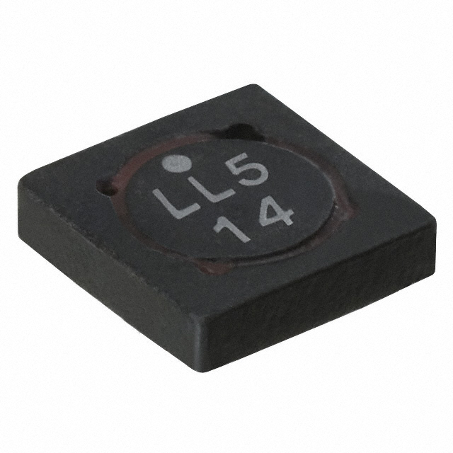
The SD3814-101-R is a 100 µH shielded drum core, wirewound inductor manufactured by Eaton - Electronics Division. This component is rated for 228 mA continuous current with a DC resistance of 3.048 Ohm and operates across the temperature range of -40°C to 85°C. The part is classified as obsolete, necessitating identification of equivalent substitute components for ongoing design requirements and procurement needs.
Substiute Parts
Key Parameters
| Parameter | Value |
|---|---|
| Inductance | 100 µH |
| Current Rating | 228 mA |
| DC Resistance (DCR) | 3.048 Ohm |
| Core Material | Ferrite |
| Shielding | Shielded |
| Mounting Type | Surface Mount |
| Operating Temperature | -40°C to 85°C |
| Inductance Test Frequency | 100 kHz |
Substitute Part Grouping Explanation
Substitution of the SD3814-101-R is determined by the following critical parameters:
Primary Matching Criteria:
- Inductance value: 100 µH (exact match required)
- Core type: Ferrite drum core, wirewound (identical construction)
- Shielding: Shielded configuration (electromagnetic containment requirement)
- Mounting type: Surface mount (PCB integration compatibility)
- Operating temperature range: -40°C to 85°C (thermal envelope)
- Test frequency: 100 kHz (measurement standard)
Secondary Compatibility Parameters:
- Current rating must meet or exceed the application requirement
- DC resistance must be acceptable for the circuit design
- Tolerance specification must satisfy circuit performance
- Saturation current must provide adequate margin above operating current
The SD14-101-R qualifies as a substitute based on matching all primary criteria while offering improved electrical performance in current handling and reduced DC resistance.
Parameter Comparison
| Parameter | SD3814-101-R (Main Part) | SD14-101-R (Substitute) |
|---|---|---|
| Inductance | 100 µH | 100 µH |
| Tolerance | ±15% | ±20% |
| Current Rating (Amps) | 228 mA | 386 mA |
| Current - Saturation (Isat) | 268 mA | 373 mA |
| DC Resistance (DCR) | 3.048 Ohm | 1.68 Ohm |
| Core Material | Ferrite | Ferrite |
| Shielding | Shielded | Shielded |
| Mounting Type | Surface Mount | Surface Mount |
| Operating Temperature | -40°C to 85°C | -40°C to 85°C |
| Inductance Test Frequency | 100 kHz | 100 kHz |
| Size / Dimension | 0.157" L x 0.157" W (4.00mm x 4.00mm) | 0.205" L x 0.205" W (5.20mm x 5.20mm) |
| Height - Seated (Max) | 0.055" (1.40mm) | 0.057" (1.45mm) |
| Product Status | Obsolete | Active |
| Packaging | Nonstandard | Tape & Reel (TR) |
| RoHS Status | Not specified | RoHS Compliant |
| Moisture Sensitivity Level (MSL) | 1 (Unlimited) | 1 (Unlimited) |
Engineering Selection Recommendations
The SD14-101-R is an active substitute for the obsolete SD3814-101-R based on the following engineering factors:
Product Status Alignment: The SD14-101-R maintains active product status with established supply chain availability, whereas the SD3814-101-R is classified as obsolete. This transition ensures long-term component procurement viability.
Electrical Performance: The SD14-101-R provides superior electrical characteristics with 386 mA current rating versus 228 mA, and reduced DC resistance of 1.68 Ohm compared to 3.048 Ohm. These improvements deliver lower power dissipation and enhanced current handling capacity within the same 100 µH inductance specification.
Compliance and Certification: The SD14-101-R is RoHS compliant, meeting modern environmental and regulatory requirements. Both components share identical moisture sensitivity classification (MSL 1) and operating temperature range (-40°C to 85°C).
Physical Compatibility: The SD14-101-R requires PCB layout accommodation for increased footprint dimensions (5.20mm x 5.20mm versus 4.00mm x 4.00mm) and marginally increased height (1.45mm versus 1.40mm). Standard surface mount assembly processes remain applicable.
Packaging Consideration: The SD14-101-R is supplied in Tape & Reel (TR) format, supporting automated assembly workflows. The main part's nonstandard packaging is replaced with industry-standard reel packaging.
Frequently Asked Questions (FAQ)
Q: Can the SD14-101-R directly replace the SD3814-101-R in existing designs?
A: The SD14-101-R is electrically compatible for applications requiring 100 µH inductance with shielded ferrite drum core construction. PCB layout modifications are necessary to accommodate the larger footprint (5.20mm x 5.20mm versus 4.00mm x 4.00mm). Verify that the application current requirement does not exceed 228 mA if the original design was optimized for the SD3814-101-R's 228 mA rating; the SD14-101-R's 386 mA rating provides additional margin.
Q: What are the key differences in electrical performance?
A: The SD14-101-R offers reduced DC resistance (1.68 Ohm versus 3.048 Ohm), resulting in lower power dissipation. The higher current rating (386 mA versus 228 mA) and saturation current (373 mA versus 268 mA) provide greater operational headroom. Inductance tolerance widens from ±15% to ±20%; circuit designs must accommodate this specification change.
Q: Are there packaging or supply chain advantages?
A: The SD14-101-R is supplied in standard Tape & Reel (TR) packaging, enabling automated pick-and-place assembly. The SD3814-101-R's obsolete status creates procurement risk; the SD14-101-R's active status ensures reliable long-term availability. RoHS compliance of the SD14-101-R aligns with current manufacturing standards.
Q: What physical constraints should be evaluated?
A: The SD14-101-R requires 5.20mm x 5.20mm PCB footprint space compared to 4.00mm x 4.00mm for the original part. Height difference is minimal (1.45mm versus 1.40mm). Verify available board real estate and clearance to adjacent components before design implementation.
Q: How do tolerance specifications affect circuit design?
A: The SD3814-101-R specifies ±15% inductance tolerance, while the SD14-101-R specifies ±20%. Designs with tight inductance requirements must evaluate whether the wider tolerance of the substitute part remains within acceptable circuit performance parameters. Both parts are tested at 100 kHz, ensuring consistent measurement methodology.
Alternative Parts

SJ6012L2TP
Littelfuse Inc.
6 Alternative Parts

JMK107BBJ476MA-RE
Taiyo Yuden
10 Alternative Parts

GMK107BBJ475MA-T
Taiyo Yuden
5 Alternative Parts
SJ6020N2ARP
Littelfuse Inc.
3 Alternative Parts
SJ6025R2ATP
Littelfuse Inc.
4 Alternative Parts

2474-05L
API Delevan Inc.
1 Alternative Parts

4590R-684K
API Delevan Inc.
1 Alternative Parts

CM6560R-334
API Delevan Inc.
1 Alternative Parts

CM6460-104
API Delevan Inc.
1 Alternative Parts

5526-12
API Delevan Inc.
1 Alternative Parts