


Request Quote
(Ships tomorrow)
SD12-150-R Equivalent & Substitute Parts Reference
Part Overview
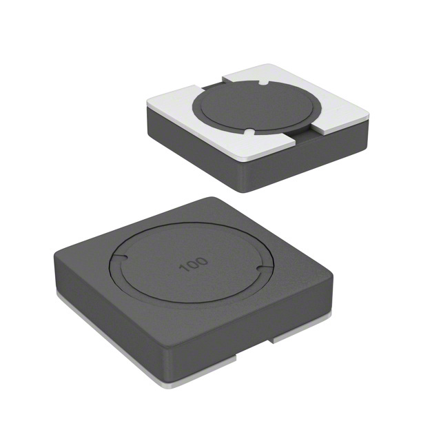
The SD12-150-R is a 15 µH shielded drum core wirewound inductor manufactured by Eaton - Electronics Division. This surface mount component is designed for applications requiring fixed inductance with controlled DC resistance and current handling capabilities. The part is classified as Active status and is RoHS Compliant, making it suitable for modern electronic assemblies. Equivalent and substitute parts are identified to provide design flexibility, inventory alternatives, and supply chain continuity when the primary part becomes unavailable or when design specifications permit functional alternatives.
Substiute Parts
Key Parameters
| Parameter | Value | Unit | Significance for Substitution |
|---|---|---|---|
| Inductance | 15 | µH | Primary electrical specification; must match exactly |
| Current Rating | 782 | mA | Determines maximum continuous current; substitute must meet or exceed |
| DC Resistance (DCR) | 408.9 | mOhm | Affects power dissipation and circuit performance; substitute must be comparable |
| Saturation Current (Isat) | 692 | mA | Defines inductance degradation threshold; substitute must meet or exceed |
| Core Material | Ferrite | — | Determines frequency response and thermal characteristics; must match |
| Shielding | Shielded | — | Reduces electromagnetic interference; must be maintained |
| Operating Temperature Range | -40°C to 85°C | — | Defines environmental limits; substitute must cover or exceed |
| Mounting Type | Surface Mount | — | Determines PCB assembly compatibility; must match |
| Package Type | Nonstandard | — | Physical footprint; substitute must be compatible with board layout |
| RoHS Status | RoHS Compliant | — | Regulatory compliance requirement; substitute must maintain compliance level |
Substitute Part Grouping Explanation
Substitute parts for the SD12-150-R are identified based on strict electrical and mechanical parameter alignment. The substitution logic is based on the following criteria:
Primary Matching Criteria:
- Inductance value of 15 µH (exact match required)
- Ferrite drum core construction with shielding
- Surface mount package configuration
- Current rating capability of 782 mA or greater
- DC resistance within acceptable operational range (approximately 400–410 mOhm)
- Operating temperature range that covers or exceeds -40°C to 85°C
- RoHS compliance status maintained or improved
Acceptable Variation Parameters:
- Current rating may exceed the original specification
- Saturation current may exceed the original specification
- DC resistance may vary within ±5% of the original value
- Tolerance may differ from the original ±20%
- Physical dimensions may vary slightly if footprint compatibility is maintained
- Operating temperature range may be extended beyond the original range
The SRR4011-150YL from Bourns Inc. qualifies as a substitute based on these criteria.
Parameter Comparison
| Parameter | SD12-150-R (Eaton) | SRR4011-150YL (Bourns) | Compatibility Assessment |
|---|---|---|---|
| Inductance | 15 µH | 15 µH | Exact match |
| Inductance Tolerance | ±20% | ±30% | Substitute has wider tolerance; acceptable for most applications |
| Current Rating | 782 mA | 900 mA | Substitute exceeds requirement; compatible |
| Saturation Current (Isat) | 692 mA | 700 mA | Substitute slightly exceeds; compatible |
| DC Resistance (DCR) | 408.9 mOhm | 400 mOhm Max | Substitute is lower; acceptable variation within 2% |
| Core Material | Ferrite | Ferrite | Exact match |
| Shielding | Shielded | Shielded | Exact match |
| Operating Temperature Range | -40°C to 85°C | -40°C to 125°C | Substitute exceeds requirement; compatible |
| Mounting Type | Surface Mount | Surface Mount | Exact match |
| Package Type | Nonstandard | Nonstandard | Both nonstandard; physical dimensions differ slightly |
| Size / Dimension | 5.20mm x 5.20mm | 4.80mm x 4.80mm | Substitute is smaller; verify PCB footprint compatibility |
| Height - Seated (Max) | 1.20mm | 1.30mm | Substitute is slightly taller; verify clearance |
| RoHS Status | RoHS Compliant | ROHS3 Compliant | Substitute maintains higher compliance level; compatible |
| Moisture Sensitivity Level (MSL) | 1 (Unlimited) | 1 (Unlimited) | Exact match |
Engineering Selection Recommendations
Primary Part Selection (SD12-150-R): The SD12-150-R remains the preferred choice when available. It is Active status, RoHS Compliant, and carries established design history. Use this part for new designs when supply is confirmed and cost is not a primary constraint.
Substitute Part Selection (SRR4011-150YL): The SRR4011-150YL is qualified as a direct substitute under the following conditions:
-
Electrical Compatibility: The substitute meets all critical electrical parameters. Current rating (900 mA) exceeds the requirement. Saturation current (700 mA) is marginally higher. DC resistance (400 mOhm max) is within acceptable tolerance.
-
Thermal Performance: Operating temperature range (-40°C to 125°C) exceeds the original specification, providing additional thermal margin.
-
Regulatory Compliance: ROHS3 Compliant status maintains or improves upon the original RoHS Compliant designation. REACH Unaffected status confirms no additional regulatory restrictions.
-
Physical Considerations: The substitute is physically smaller (4.80mm x 4.80mm versus 5.20mm x 5.20mm) and slightly taller (1.30mm versus 1.20mm). PCB layout verification is required to confirm footprint compatibility and clearance.
-
Availability: The SRR4011-150YL has higher inventory availability (2079 pcs versus 791 pcs), supporting supply chain continuity.
Selection Criteria:
- Use SD12-150-R for designs requiring exact dimensional match or established supplier relationship
- Use SRR4011-150YL when supply constraints exist, higher current margin is beneficial, or extended temperature range is advantageous
- Verify PCB footprint compatibility before design release when switching between parts
Frequently Asked Questions (FAQ)
Q1: Can the SRR4011-150YL be used as a direct replacement for the SD12-150-R without PCB modification?
A: Electrical substitution is valid. However, physical dimensions differ: the SRR4011-150YL is smaller in footprint (4.80mm x 4.80mm versus 5.20mm x 5.20mm) but taller (1.30mm versus 1.20mm). PCB layout verification is required to confirm that the existing footprint accommodates the substitute part and that clearance above the component is sufficient.
Q2: What is the impact of the higher inductance tolerance (±30%) in the SRR4011-150YL compared to the SD12-150-R (±20%)?
A: The wider tolerance in the substitute part may affect circuit performance in applications with tight inductance specifications. Evaluate the circuit's sensitivity to inductance variation. If the application requires inductance tolerance tighter than ±30%, the SD12-150-R is the appropriate choice.
Q3: Does the lower DC resistance of the SRR4011-150YL (400 mOhm max versus 408.9 mOhm) affect circuit performance?
A: The lower DC resistance in the substitute part reduces power dissipation and heat generation, which is generally beneficial. The difference of approximately 8.9 mOhm is negligible in most applications and does not introduce compatibility issues.
Q4: Is the extended operating temperature range of the SRR4011-150YL (-40°C to 125°C versus -40°C to 85°C) a concern?
A: No. The extended temperature range in the substitute part provides additional thermal margin and is not a compatibility concern. Use this specification when the application environment exceeds 85°C.
Q5: Are there any regulatory or compliance differences between the two parts?
A: Both parts are RoHS compliant. The SRR4011-150YL carries ROHS3 Compliant status, which represents an improved compliance designation. The SRR4011-150YL is also REACH Unaffected, confirming no additional regulatory restrictions. No compliance barriers exist for substitution.
Q6: What is the significance of the higher current rating in the SRR4011-150YL (900 mA versus 782 mA)?
A: The higher current rating provides additional design margin and allows the substitute part to handle transient current spikes without saturation. This is advantageous in applications with variable or peak current demands.
Q7: How should I verify compatibility before implementing the SRR4011-150YL in production?
A: Conduct the following verification steps: (1) Confirm PCB footprint compatibility using the provided dimensions; (2) Verify clearance above the component for the additional 0.10mm height; (3) Validate circuit performance with the ±30% inductance tolerance; (4) Confirm thermal performance in the target operating environment; (5) Test a sample assembly before full production release.
Alternative Parts

SJ6012L2TP
Littelfuse Inc.
6 Alternative Parts

JMK107BBJ476MA-RE
Taiyo Yuden
10 Alternative Parts

GMK107BBJ475MA-T
Taiyo Yuden
5 Alternative Parts
SJ6020N2ARP
Littelfuse Inc.
3 Alternative Parts
SJ6025R2ATP
Littelfuse Inc.
4 Alternative Parts

2474-05L
API Delevan Inc.
1 Alternative Parts

4590R-684K
API Delevan Inc.
1 Alternative Parts

CM6560R-334
API Delevan Inc.
1 Alternative Parts

CM6460-104
API Delevan Inc.
1 Alternative Parts

5526-12
API Delevan Inc.
1 Alternative Parts