


Request Quote
(Ships tomorrow)
SCMS5D18-4R7 Equivalent & Substitute Parts
Part Overview
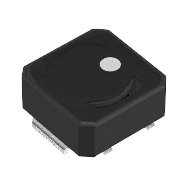
The SCMS5D18-4R7 is a 4.7 µH shielded surface mount inductor manufactured by Signal Transformer, rated for 1.8 A continuous current with a maximum DC resistance of 91 mOhm. This component is classified as obsolete, making equivalent substitute parts necessary for new designs and ongoing production requirements. The part operates across the industrial temperature range of -40°C to 125°C and meets ROHS3 compliance standards.
Substiute Parts
Key Parameters
| Parameter | Value |
|---|---|
| Inductance | 4.7 µH |
| Inductance Tolerance | ±30% |
| Current Rating | 1.8 A |
| Saturation Current (Isat) | 1.54 A |
| DC Resistance (DCR) | 91 mOhm Max |
| Shielding | Shielded |
| Operating Temperature Range | -40°C to 125°C |
| Inductance Test Frequency | 100 kHz |
| Mounting Type | Surface Mount |
| Package Size | 5.20 mm × 5.20 mm |
| Height (Seated Max) | 1.90 mm |
| RoHS Status | ROHS3 Compliant |
| Moisture Sensitivity Level | 1 (Unlimited) |
Substitute Part Grouping Explanation
Substitute parts for the SCMS5D18-4R7 are qualified based on the following electrical and mechanical parameters:
Primary Matching Criteria:
- Inductance value: 4.7 µH (fixed requirement)
- Inductance tolerance: ±30% (fixed requirement)
- Shielding: Shielded (fixed requirement)
- Mounting type: Surface Mount (fixed requirement)
- Inductance test frequency: 100 kHz (fixed requirement)
- RoHS compliance: ROHS3 Compliant (fixed requirement)
Allowable Variation Parameters:
- Current rating: Equal to or greater than 1.8 A
- DC resistance: Equal to or less than 91 mOhm
- Operating temperature range: Must include -40°C to 125°C or equivalent industrial range
- Package size: Physically compatible with 5.20 mm × 5.20 mm footprint tolerance
- Saturation current: Equal to or greater than 1.54 A
The three substitute parts listed below meet all primary matching criteria and provide equal or improved electrical performance within the allowable variation parameters.
Parameter Comparison
| Parameter | SCMS5D18-4R7 (Main) | TYS50404R7N-10 | VLCF5020T-4R7N1R4 | VLCF5020T-4R7N1R7-1 |
|---|---|---|---|---|
| Manufacturer | Signal Transformer | Laird-Signal Integrity Products | TDK Corporation | TDK Corporation |
| Inductance | 4.7 µH | 4.7 µH | 4.7 µH | 4.7 µH |
| Inductance Tolerance | ±30% | ±30% | ±30% | ±30% |
| Current Rating | 1.8 A | 3.0 A | 1.4 A | 1.7 A |
| Saturation Current (Isat) | 1.54 A | 4.6 A | 1.4 A | 1.7 A |
| DC Resistance (DCR) | 91 mOhm Max | 30 mOhm Max | 96 mOhm Max | 122 mOhm Max |
| Shielding | Shielded | Shielded | Shielded | Shielded |
| Operating Temperature Range | -40°C to 125°C | -40°C to 125°C | -40°C to 105°C | -40°C to 105°C |
| Inductance Test Frequency | 100 kHz | 100 kHz | 100 kHz | 100 kHz |
| Mounting Type | Surface Mount | Surface Mount | Surface Mount | Surface Mount |
| Package Size | 5.20 mm × 5.20 mm | 5.00 mm × 5.00 mm | 5.00 mm × 5.00 mm | 5.00 mm × 5.00 mm |
| Height (Seated Max) | 1.90 mm | 4.20 mm | 2.00 mm | 2.00 mm |
| Product Status | Obsolete | Active | Active | Active |
| RoHS Status | ROHS3 Compliant | ROHS3 Compliant | ROHS3 Compliant | ROHS3 Compliant |
| Moisture Sensitivity Level | 1 (Unlimited) | 1 (Unlimited) | 1 (Unlimited) | 1 (Unlimited) |
Engineering Selection Recommendations
TYS50404R7N-10 (Laird-Signal Integrity Products)
This substitute provides superior electrical performance with 3.0 A current rating and 30 mOhm DC resistance, representing a significant improvement over the original SCMS5D18-4R7. The part maintains active product status and full ROHS3 compliance. The primary consideration is the increased height of 4.20 mm compared to the original 1.90 mm, which may require PCB layout verification for clearance constraints. The slightly smaller footprint (5.00 mm × 5.00 mm) is mechanically compatible with the original 5.20 mm × 5.20 mm package.
VLCF5020T-4R7N1R4 (TDK Corporation)
This TDK substitute maintains active product status and ROHS3 compliance with a drum core, wirewound construction. The 1.4 A current rating falls below the original 1.8 A specification, making this part suitable only for applications where the actual operating current does not exceed 1.4 A. The DC resistance of 96 mOhm is marginally higher than the original 91 mOhm specification. The operating temperature range is limited to -40°C to 105°C, which is 20°C below the original upper limit. The compact height of 2.00 mm provides excellent PCB clearance compatibility.
VLCF5020T-4R7N1R7-1 (TDK Corporation)
This TDK substitute offers the closest current rating match at 1.7 A, approaching the original 1.8 A specification. The part maintains active product status and ROHS3 compliance with ferrite drum core, wirewound construction. The DC resistance of 122 mOhm exceeds the original 91 mOhm maximum by 31 mOhm, which increases power dissipation and thermal effects. The operating temperature range is limited to -40°C to 105°C. The compact height of 2.00 mm and 5.00 mm × 5.00 mm footprint provide excellent PCB compatibility.
Frequently Asked Questions (FAQ)
Q: Can I use TYS50404R7N-10 as a direct replacement for SCMS5D18-4R7?
A: TYS50404R7N-10 is electrically compatible as a substitute, meeting all primary matching criteria including 4.7 µH inductance, ±30% tolerance, shielding, and ROHS3 compliance. However, the increased height of 4.20 mm versus 1.90 mm requires verification of PCB clearance and component placement constraints before implementation.
Q: Why does VLCF5020T-4R7N1R4 have a lower current rating than the original part?
A: VLCF5020T-4R7N1R4 is rated for 1.4 A continuous current, which is 0.4 A below the original SCMS5D18-4R7 specification of 1.8 A. This part is suitable only for circuits where the actual operating current remains at or below 1.4 A. Exceeding this rating will cause saturation and performance degradation.
Q: What is the impact of higher DC resistance in VLCF5020T-4R7N1R7-1?
A: The DC resistance of 122 mOhm in VLCF5020T-4R7N1R7-1 is 31 mOhm higher than the original 91 mOhm specification. This increases resistive losses according to I²R, resulting in higher power dissipation and component heating. For a 1.7 A circuit, this represents approximately 0.36 W additional dissipation compared to the original part.
Q: Are all substitute parts ROHS3 compliant?
A: Yes. All three substitute parts—TYS50404R7N-10, VLCF5020T-4R7N1R4, and VLCF5020T-4R7N1R7-1—are ROHS3 compliant with Moisture Sensitivity Level 1 (Unlimited), matching the original SCMS5D18-4R7 environmental and regulatory specifications.
Q: Do the substitute parts fit the same PCB footprint?
A: The substitute parts use 5.00 mm × 5.00 mm footprints compared to the original 5.20 mm × 5.20 mm footprint. This 0.20 mm reduction in each dimension is mechanically compatible with standard PCB pad layouts designed for the original part. However, height differences require clearance verification: TYS50404R7N-10 at 4.20 mm, and both TDK parts at 2.00 mm, versus the original 1.90 mm.
Q: What is the operating temperature limitation of the TDK substitutes?
A: Both VLCF5020T-4R7N1R4 and VLCF5020T-4R7N1R7-1 are rated for -40°C to 105°C, which is 20°C below the original SCMS5D18-4R7 upper limit of 125°C. These parts are not suitable for applications requiring operation above 105°C.
Alternative Parts

SJ6012L2TP
Littelfuse Inc.
6 Alternative Parts

JMK107BBJ476MA-RE
Taiyo Yuden
10 Alternative Parts

GMK107BBJ475MA-T
Taiyo Yuden
5 Alternative Parts
SJ6020N2ARP
Littelfuse Inc.
3 Alternative Parts
SJ6025R2ATP
Littelfuse Inc.
4 Alternative Parts

2474-05L
API Delevan Inc.
1 Alternative Parts

4590R-684K
API Delevan Inc.
1 Alternative Parts

CM6560R-334
API Delevan Inc.
1 Alternative Parts

CM6460-104
API Delevan Inc.
1 Alternative Parts

5526-12
API Delevan Inc.
1 Alternative Parts