


Request Quote
(Ships tomorrow)
SCH74-390 Equivalent & Substitute Parts
Part Overview
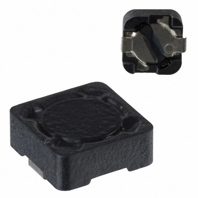
The SCH74-390 is a 39 µH unshielded wirewound inductor manufactured by Signal Transformer, rated for 1.68 A continuous current with a maximum DC resistance of 210mOhm. This component is classified as obsolete, making equivalent substitute parts necessary for new designs, repairs, and production continuity. The part operates across the industrial temperature range of -40°C to 125°C and meets ROHS3 compliance requirements.
Substiute Parts
Key Parameters
| Parameter | Value |
|---|---|
| Inductance | 39 µH |
| Inductance Tolerance | ±10% |
| Current Rating | 1.68 A |
| Saturation Current (Isat) | 1.3 A |
| DC Resistance (DCR) | 210 mOhm Max |
| Shielding | Unshielded |
| Core Type | Wirewound |
| Mounting Type | Surface Mount |
| Operating Temperature | -40°C to 125°C |
| Package Type | Nonstandard |
| Physical Dimensions | 8.00mm L × 7.30mm W × 5.20mm H |
| RoHS Status | ROHS3 Compliant |
| MSL Rating | 1 (Unlimited) |
Substitute Part Grouping Explanation
Substitution of the SCH74-390 is determined by the following critical parameters:
- Inductance value: 39 µH (tolerance range acceptable within ±10% to ±20%)
- Current rating: Minimum 1.4 A (substitute must support circuit current demands)
- DC resistance: Maximum 230 mOhm (acceptable variance from 210 mOhm specification)
- Saturation current: Minimum 1.3 A (must prevent core saturation under operating conditions)
- Mounting type: Surface Mount (physical compatibility requirement)
- Operating temperature range: Must encompass or match -40°C to 125°C
- Compliance certifications: ROHS3 and REACH status must be maintained
The SPD74R-393M qualifies as a direct substitute based on these parameters. While it introduces shielding (ferrite drum core) and slightly different tolerance specifications, the electrical performance envelope remains compatible with the original design requirements.
Parameter Comparison
| Parameter | SCH74-390 (Main Part) | SPD74R-393M (Substitute) | Compatibility Notes |
|---|---|---|---|
| Manufacturer | Signal Transformer | API Delevan Inc. | Different manufacturer, equivalent performance class |
| Inductance | 39 µH | 39 µH | Exact match |
| Inductance Tolerance | ±10% | ±20% | Substitute has wider tolerance; acceptable for most applications |
| Current Rating | 1.68 A | 1.4 A | Substitute rated 0.28 A lower; verify circuit current requirements |
| Saturation Current (Isat) | 1.3 A | 1.4 A | Substitute provides higher saturation margin |
| DC Resistance (DCR) | 210 mOhm Max | 230 mOhm Max | Substitute 20 mOhm higher; acceptable for most circuits |
| Shielding | Unshielded | Shielded | Shielding reduces EMI; may affect circuit layout |
| Core Type | Wirewound | Drum Core, Wirewound | Different core geometry; same wirewound technology |
| Operating Temperature | -40°C to 125°C | -55°C to 125°C | Substitute provides extended low-temperature range |
| Physical Dimensions | 8.00mm L × 7.30mm W × 5.20mm H | 7.30mm L × 7.30mm W × 4.70mm H | Substitute is smaller; verify PCB layout compatibility |
| Product Status | Obsolete | Active | Substitute is in active production |
| RoHS Status | ROHS3 Compliant | ROHS3 Compliant | Both meet regulatory requirements |
| MSL Rating | 1 (Unlimited) | 1 (Unlimited) | Identical moisture sensitivity classification |
Engineering Selection Recommendations
The SPD74R-393M is the qualified substitute for the obsolete SCH74-390 based on the following criteria:
- Both parts maintain ROHS3 compliance and REACH unaffected status, ensuring regulatory continuity
- Inductance value is identical at 39 µH, with the substitute's ±20% tolerance encompassing the original ±10% specification
- Current rating differential (1.68 A vs. 1.4 A) requires verification against actual circuit current draw; if circuit current does not exceed 1.4 A, the substitute is fully compatible
- DC resistance increase of 20 mOhm (210 to 230 mOhm) is within acceptable engineering margins for most applications
- The substitute's shielded ferrite drum core design provides EMI reduction benefits not present in the original unshielded design
- Physical dimensions are smaller, reducing PCB footprint; verify mounting area compatibility before implementation
- Extended operating temperature range (-55°C to 125°C) provides additional thermal margin
- Active production status of the substitute ensures long-term availability and supply chain stability
Frequently Asked Questions (FAQ)
Q: Can the SPD74R-393M directly replace the SCH74-390 without circuit modifications?
A: Direct replacement is possible if circuit current does not exceed 1.4 A. The substitute's shielded design may require PCB layout verification to ensure no unintended coupling effects. Physical dimensions are smaller, so mounting area compatibility must be confirmed.
Q: What is the impact of the ±20% tolerance on the SPD74R-393M compared to the ±10% tolerance of the SCH74-390?
A: The wider tolerance of the substitute is acceptable for most filter and impedance matching applications. If circuit performance requires tighter inductance tolerance, additional testing or component selection may be necessary.
Q: Does the shielded design of the SPD74R-393M affect circuit performance?
A: Shielding reduces electromagnetic interference emission and susceptibility. In most applications, this is beneficial. However, if the original unshielded design was intentional for specific coupling requirements, the shielded substitute may alter circuit behavior.
Q: Are there any compliance or certification differences between the two parts?
A: Both parts are ROHS3 compliant, REACH unaffected, and carry identical MSL ratings. No compliance barriers exist for substitution.
Q: What is the significance of the 0.28 A current rating reduction?
A: The substitute's 1.4 A rating versus the original 1.68 A requires verification that circuit current remains below 1.4 A under all operating conditions, including transient events and worst-case scenarios.
Q: How do the physical dimension differences affect PCB design?
A: The substitute is smaller (7.30mm × 7.30mm × 4.70mm vs. 8.00mm × 7.30mm × 5.20mm). Verify that the smaller footprint is compatible with existing PCB layouts and that no mechanical interference occurs with adjacent components.
Alternative Parts

SJ6012L2TP
Littelfuse Inc.
6 Alternative Parts

JMK107BBJ476MA-RE
Taiyo Yuden
10 Alternative Parts

GMK107BBJ475MA-T
Taiyo Yuden
5 Alternative Parts
SJ6020N2ARP
Littelfuse Inc.
3 Alternative Parts
SJ6025R2ATP
Littelfuse Inc.
4 Alternative Parts

2474-05L
API Delevan Inc.
1 Alternative Parts

4590R-684K
API Delevan Inc.
1 Alternative Parts

CM6560R-334
API Delevan Inc.
1 Alternative Parts

CM6460-104
API Delevan Inc.
1 Alternative Parts

5526-12
API Delevan Inc.
1 Alternative Parts