


Request Quote
(Ships tomorrow)
RN1102ACT(TPL3) Equivalent & Substitute Parts
Part Overview
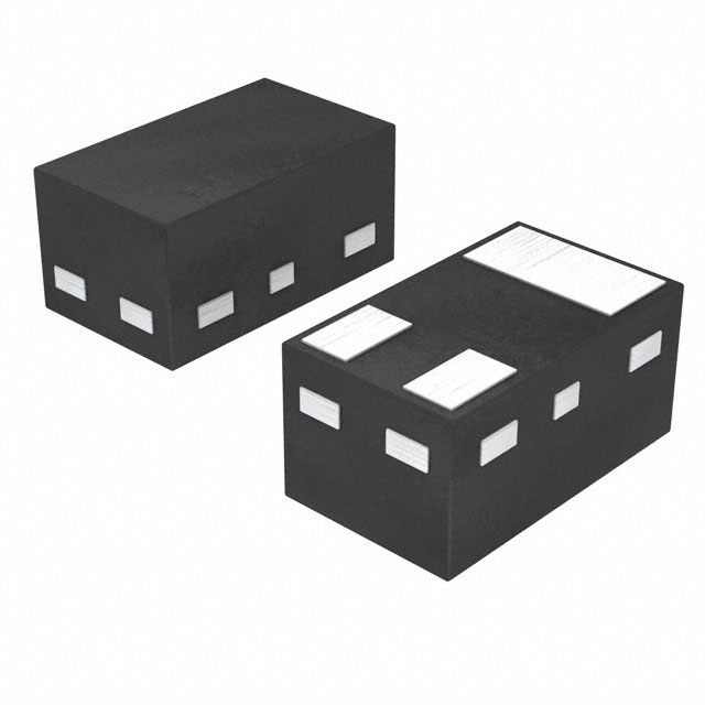
The RN1102ACT(TPL3) is a pre-biased NPN bipolar junction transistor (BJT) manufactured by Toshiba Semiconductor and Storage. This surface mount device is designed for general-purpose switching and amplification applications with a maximum collector current of 80 mA and collector-emitter breakdown voltage of 50 V. The part is classified as obsolete, making equivalent substitutes necessary for new designs and ongoing production requirements. Active alternatives with compatible electrical and mechanical specifications are available from multiple manufacturers including Diodes Incorporated, Nexperia USA Inc., and Philips.
Substiute Parts
Key Parameters
| Parameter | Value | Unit |
|---|---|---|
| Transistor Type | NPN - Pre-Biased | — |
| Current - Collector (Ic) (Max) | 80 | mA |
| Voltage - Collector Emitter Breakdown (Max) | 50 | V |
| Resistor - Base (R1) | 10 | kOhms |
| Resistor - Emitter Base (R2) | 10 | kOhms |
| DC Current Gain (hFE) (Min) @ Ic, Vce | 50 @ 10mA, 5V | — |
| Vce Saturation (Max) @ Ib, Ic | 150 | mV |
| Current - Collector Cutoff (Max) | 500 | nA |
| Power - Max | 100 | mW |
| Mounting Type | Surface Mount | — |
| Package / Case | SC-101, SOT-883 | — |
| Moisture Sensitivity Level (MSL) | 1 (Unlimited) | — |
Substitute Part Grouping Explanation
Substitution of the RN1102ACT(TPL3) is determined by strict alignment of the following electrical and mechanical parameters:
Primary Substitution Criteria:
- Transistor Type: NPN - Pre-Biased configuration
- Voltage - Collector Emitter Breakdown (Max): 50 V minimum
- Current - Collector (Ic) (Max): 80 mA minimum
- Resistor - Base (R1): 10 kOhms
- Resistor - Emitter Base (R2): 10 kOhms (where specified)
- Mounting Type: Surface Mount
- Package compatibility: SC-101, SOT-883, or equivalent footprints
Secondary Compatibility Parameters:
- DC Current Gain (hFE) characteristics
- Vce Saturation performance
- Power dissipation capability
- Moisture Sensitivity Level: 1 (Unlimited)
Substitute parts must meet or exceed the maximum ratings of the main part while maintaining the pre-biased NPN configuration and internal resistor network. Parts with higher current ratings, voltage ratings, or power dissipation are acceptable substitutes. Variations in DC current gain and saturation voltage are acceptable provided the parts function within the application's operating envelope.
Parameter Comparison
| Parameter | RN1102ACT(TPL3) | RN1402,LF | DDTC114YLP-7 | PDTC114EM,315 | PDTC114TMB,315 | PDTC114YMB,315 |
|---|---|---|---|---|---|---|
| Manufacturer | Toshiba | Toshiba | Diodes Inc. | Nexperia | Nexperia | Nexperia |
| Product Status | Obsolete | Active | Active | Active | Active | Active |
| Transistor Type | NPN - Pre-Biased | NPN - Pre-Biased | NPN - Pre-Biased | NPN - Pre-Biased | NPN - Pre-Biased | NPN - Pre-Biased |
| Current - Collector (Ic) (Max) | 80 mA | 100 mA | 100 mA | 100 mA | 100 mA | 100 mA |
| Voltage - Collector Emitter Breakdown (Max) | 50 V | 50 V | 50 V | 50 V | 50 V | 50 V |
| Resistor - Base (R1) | 10 kOhms | 10 kOhms | 10 kOhms | 10 kOhms | 10 kOhms | 10 kOhms |
| Resistor - Emitter Base (R2) | 10 kOhms | 10 kOhms | 47 kOhms | 10 kOhms | Not specified | 47 kOhms |
| DC Current Gain (hFE) (Min) @ Ic, Vce | 50 @ 10mA, 5V | 50 @ 10mA, 5V | 180 @ 50mA, 5V | 30 @ 5mA, 5V | 200 @ 1mA, 5V | 100 @ 5mA, 5V |
| Vce Saturation (Max) @ Ib, Ic | 150mV @ 250µA, 5mA | 300mV @ 250µA, 5mA | 200mV @ 5mA, 50mA | 150mV @ 500µA, 10mA | 150mV @ 500µA, 10mA | 100mV @ 250µA, 5mA |
| Current - Collector Cutoff (Max) | 500 nA | 500 nA | 500 nA | 1 µA | 1 µA | 1 µA |
| Power - Max | 100 mW | 200 mW | 250 mW | 250 mW | 250 mW | 250 mW |
| Mounting Type | Surface Mount | Surface Mount | Surface Mount | Surface Mount | Surface Mount | Surface Mount |
| Package / Case | SC-101, SOT-883 | TO-236-3, SC-59, SOT-23-3 | 3-UFDFN | SC-101, SOT-883 | 3-XFDFN | 3-XFDFN |
| Moisture Sensitivity Level (MSL) | 1 (Unlimited) | 1 (Unlimited) | 1 (Unlimited) | 1 (Unlimited) | 1 (Unlimited) | 1 (Unlimited) |
| RoHS Status | Not specified | ROHS3 Compliant | ROHS3 Compliant | ROHS3 Compliant | ROHS3 Compliant | ROHS3 Compliant |
Engineering Selection Recommendations
Direct Package Replacement (Recommended for Footprint Compatibility):
PDTC114EM,315 from Nexperia USA Inc. is the optimal substitute when maintaining the original SC-101/SOT-883 package footprint is required. This part is active, ROHS3 compliant, and REACH unaffected. It provides identical base and emitter-base resistor values (10 kOhms each), matching the RN1102ACT(TPL3) internal network precisely. The 100 mA collector current rating exceeds the original 80 mA specification, and the 250 mW power rating provides increased thermal margin over the original 100 mW design.
Higher Current Capacity Alternatives:
RN1402,LF from Toshiba Semiconductor and Storage offers an active product status with 100 mA collector current and 200 mW power dissipation. This part maintains the same base and emitter-base resistor configuration (10 kOhms each) and identical DC current gain specification (50 @ 10mA, 5V). The package is S-Mini (TO-236-3, SC-59, SOT-23-3), which differs from the original footprint.
DDTC114YLP-7 from Diodes Incorporated provides 100 mA collector current and 250 mW power dissipation in an active product status. This part features a 47 kOhm emitter-base resistor (R2) instead of 10 kOhms, resulting in different DC current gain characteristics (180 @ 50mA, 5V). The package is 3-UFDFN, requiring PCB layout modification.
Automotive-Grade Option:
PDTC114TMB,315 from Nexperia USA Inc. is qualified to AEC-Q100 automotive standards and suitable for applications requiring automotive-grade components. This part is active, ROHS3 compliant, and REACH unaffected. It provides 100 mA collector current and 250 mW power dissipation with a 230 MHz transition frequency. The package is 3-XFDFN (DFN1006B-3).
General-Purpose Alternative:
PDTC114YMB,315 from Nexperia USA Inc. is active and ROHS3 compliant with 100 mA collector current and 250 mW power dissipation. This part features a 47 kOhm emitter-base resistor (R2) and 230 MHz transition frequency. The package is 3-XFDFN (DFN1006B-3).
All recommended substitutes maintain the 50 V collector-emitter breakdown voltage and surface mount mounting type of the original part. Selection should be based on package footprint compatibility with existing PCB designs and application-specific requirements for current gain and saturation characteristics.
Frequently Asked Questions (FAQ)
Q: Can PDTC114EM,315 be used as a direct replacement for RN1102ACT(TPL3)?
A: Yes. PDTC114EM,315 maintains the same SC-101/SOT-883 package footprint, identical base resistor (10 kOhms) and emitter-base resistor (10 kOhms) values, and compatible electrical specifications. The 100 mA collector current and 250 mW power rating exceed the original 80 mA and 100 mW specifications, providing additional design margin.
Q: What is the difference between PDTC114EM,315 and DDTC114YLP-7?
A: Both parts are active NPN pre-biased transistors with 50 V breakdown voltage and 100 mA collector current. The primary differences are: (1) PDTC114EM,315 has 10 kOhm base and emitter-base resistors matching the original part, while DDTC114YLP-7 has a 47 kOhm emitter-base resistor; (2) PDTC114EM,315 uses SC-101/SOT-883 package (same as original), while DDTC114YLP-7 uses 3-UFDFN package; (3) DC current gain differs (30 @ 5mA, 5V versus 180 @ 50mA, 5V).
Q: Is RN1402,LF compatible with the original RN1102ACT(TPL3) design?
A: RN1402,LF is electrically compatible with identical base and emitter-base resistor values (10 kOhms each) and matching DC current gain specification (50 @ 10mA, 5V). However, the package differs (S-Mini/TO-236-3 versus SC-101/SOT-883), requiring PCB layout modification. The 100 mA collector current and 200 mW power rating exceed original specifications.
Q: What does "pre-biased" mean in the context of these transistors?
A: Pre-biased transistors integrate internal base and emitter-base resistors on the same die as the transistor. These internal resistors establish a bias network that allows the transistor to switch with minimal external circuitry. The RN1102ACT(TPL3) and its substitutes all feature 10 kOhm base resistors and 10 kOhm emitter-base resistors (except where noted), defining their switching characteristics.
Q: Can I use PDTC114YMB,315 in place of PDTC114EM,315?
A: Both parts are active Nexperia products with 100 mA collector current, 50 V breakdown voltage, and 250 mW power dissipation. The key difference is the emitter-base resistor: PDTC114EM,315 has 10 kOhms (matching the original part), while PDTC114YMB,315 has 47 kOhms. This resistor difference affects DC current gain characteristics. Additionally, PDTC114YMB,315 uses 3-XFDFN package while PDTC114EM,315 uses SC-101/SOT-883 package.
Q: Are all substitute parts RoHS compliant?
A: All active substitute parts listed (RN1402,LF, DDTC114YLP-7, PDTC114EM,315, PDTC114TMB,315, PDTC114YMB,315) are ROHS3 compliant. The original RN1102ACT(TPL3) RoHS status is not specified in the provided data.
Q: What is the significance of the 230 MHz and 250 MHz transition frequency specifications?
A: Transition frequency (fT) indicates the frequency at which the transistor's current gain drops to unity. PDTC114TMB,315 and PDTC114YMB,315 specify 230 MHz, while DDTC114YLP-7 and RN1402,LF specify 250 MHz. The original RN1102ACT(TPL3) does not specify transition frequency. Higher transition frequency provides better high-frequency performance but is not a substitution requirement for general-purpose switching applications.
Q: Is PDTC114TMB,315 suitable for automotive applications?
A: Yes. PDTC114TMB,315 is qualified to AEC-Q100 automotive standards and carries automotive-grade designation. It is ROHS3 compliant and REACH unaffected. This part is appropriate for applications requiring automotive-grade component certification.
Q: What packaging considerations should I evaluate when selecting a substitute?
A: The original RN1102ACT(TPL3) uses SC-101/SOT-883 package. PDTC114EM,315 maintains this footprint for direct PCB compatibility. RN1402,LF uses S-Mini/TO-236-3 package, DDTC114YLP-7 uses 3-UFDFN package, and PDTC114TMB,315 and PDTC114YMB,315 use 3-XFDFN package. Package selection affects PCB layout, assembly process, and thermal characteristics. Verify footprint compatibility with existing designs before substitution.
Alternative Parts

SJ6012L2TP
Littelfuse Inc.
6 Alternative Parts

JMK107BBJ476MA-RE
Taiyo Yuden
10 Alternative Parts

GMK107BBJ475MA-T
Taiyo Yuden
5 Alternative Parts
SJ6020N2ARP
Littelfuse Inc.
3 Alternative Parts
SJ6025R2ATP
Littelfuse Inc.
4 Alternative Parts

2474-05L
API Delevan Inc.
1 Alternative Parts

4590R-684K
API Delevan Inc.
1 Alternative Parts

CM6560R-334
API Delevan Inc.
1 Alternative Parts

CM6460-104
API Delevan Inc.
1 Alternative Parts

5526-12
API Delevan Inc.
1 Alternative Parts