


Request Quote
(Ships tomorrow)
RJK6014DPP-E0#T2 Equivalent & Substitute Parts
Part Overview
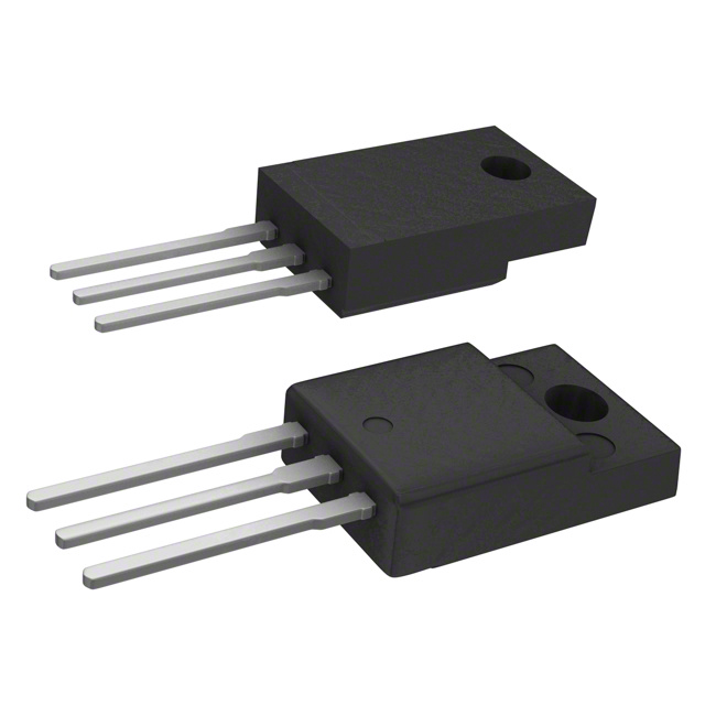
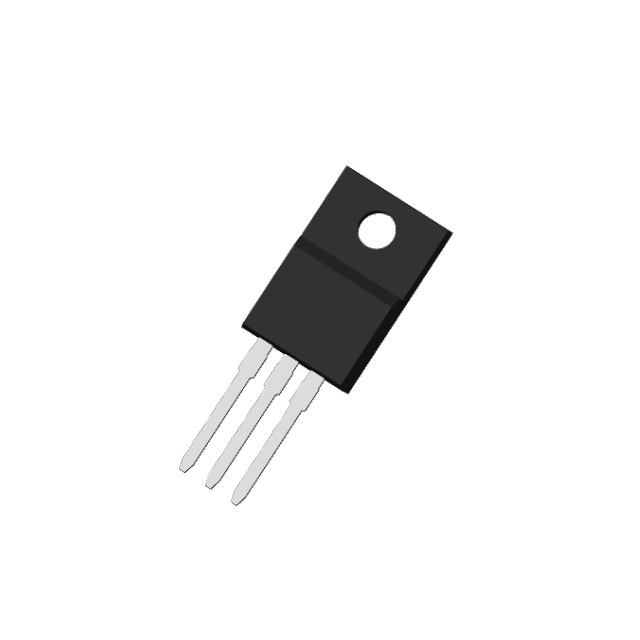
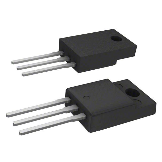
The RJK6014DPP-E0#T2 is an N-Channel 600V 16A MOSFET manufactured by Renesas Electronics Corporation in a TO-220FP through-hole package. This device is rated for 35W continuous power dissipation at the case temperature and operates up to 150°C junction temperature. The part is classified as obsolete, necessitating identification of equivalent and substitute components for ongoing design support and procurement continuity. Substitute parts must maintain electrical compatibility across voltage, current, and thermal specifications while accommodating the through-hole TO-220 package family.
Substiute Parts
Key Parameters
| Parameter | Value | Unit |
|---|---|---|
| Drain to Source Voltage (Vdss) | 600 | V |
| Continuous Drain Current (Id) @ 25°C | 16 | A (Ta) |
| Drive Voltage (Max Rds On) | 10 | V |
| Rds On (Max) @ Id, Vgs | 575 | mOhm @ 8A, 10V |
| Gate Charge (Qg) @ Vgs | 45 | nC @ 10V |
| Vgs (Max) | ±30 | V |
| Input Capacitance (Ciss) @ Vds | 1800 | pF @ 25V |
| Power Dissipation (Max) | 35 | W (Tc) |
| Operating Temperature (TJ) | 150 | °C |
| Mounting Type | Through Hole | — |
| Package / Case | TO-220-3 Full Pack | — |
| RoHS Status | ROHS3 Compliant | — |
| Moisture Sensitivity Level (MSL) | 1 (Unlimited) | — |
Substitute Part Grouping Explanation
Substitution of the RJK6014DPP-E0#T2 is determined by the following critical electrical and mechanical parameters:
Voltage Rating: Substitute parts must maintain a Drain to Source Voltage (Vdss) of 600V or higher to ensure safe operation within the original design envelope.
Current Capability: The continuous drain current (Id) at 25°C must be sufficient to support the 16A requirement. Parts with lower current ratings (7A to 12A) operate within reduced current margins and are classified as partial substitutes. Parts with 10A or higher current ratings provide closer functional equivalence.
On-State Resistance (Rds On): The maximum on-state resistance at specified gate voltage and drain current determines conduction losses. Lower Rds On values indicate improved efficiency and reduced thermal stress.
Gate Charge (Qg): Lower gate charge values reduce switching losses and improve gate drive efficiency, though this parameter is secondary to voltage and current ratings for substitution purposes.
Package Compatibility: All substitute parts must use through-hole TO-220 package variants (TO-220FP, TO-220FM, TO-220-3 Full Pack) to ensure mechanical and thermal interface compatibility with existing PCB designs.
Compliance Status: RoHS3 compliance and MSL Level 1 are required for all substitutes to maintain regulatory and environmental standards.
Parameter Comparison
| Part Number | Manufacturer | Vdss (V) | Id @ 25°C (A) | Rds On (mOhm) | Qg (nC) | Power Dissipation (W) | Package | Status |
|---|---|---|---|---|---|---|---|---|
| RJK6014DPP-E0#T2 | Renesas Electronics | 600 | 16 (Ta) | 575 @ 8A, 10V | 45 @ 10V | 35 (Tc) | TO-220FP | Obsolete |
| AOTF12N60L | Alpha & Omega Semiconductor | 600 | 12 (Tc) | 550 @ 6A, 10V | 50 @ 10V | 50 (Tc) | TO-220F | Active |
| IPAW70R600CEXKSA1 | Infineon Technologies | 700 | 10.5 (Tc) | 600 @ 1A, 10V | 22 @ 10V | 86 (Tc) | PG-TO220-3-FP | Obsolete |
| R6007ENX | Rohm Semiconductor | 600 | 7 (Tc) | 620 @ 2.4A, 10V | 20 @ 10V | 40 (Tc) | TO-220FM | Active |
| R6007KNX | Rohm Semiconductor | 600 | 7 (Tc) | 620 @ 2.4A, 10V | 14.5 @ 10V | 46 (Tc) | TO-220FM | Active |
| R6009ENX | Rohm Semiconductor | 600 | 9 (Tc) | 535 @ 2.8A, 10V | 23 @ 10V | 40 (Tc) | TO-220FM | Active |
| R6009KNX | Rohm Semiconductor | 600 | 9 (Tc) | 535 @ 2.8A, 10V | 16.5 @ 10V | 48 (Tc) | TO-220FM | Active |
| SIHA6N65E-E3 | Vishay Siliconix | 650 | 7 (Tc) | 600 @ 3A, 10V | 48 @ 10V | 31 (Tc) | TO-220 Full Pack | Active |
| SIHF7N60E-E3 | Vishay Siliconix | 600 | 7 (Tc) | 600 @ 3.5A, 10V | 40 @ 10V | 31 (Tc) | TO-220 Full Pack | Active |
| STF10N60M2 | STMicroelectronics | 600 | 7.5 (Tc) | 600 @ 4A, 10V | 13.5 @ 10V | 25 (Tc) | TO-220FP | Active |
| STF10NM60N | STMicroelectronics | 600 | 10 (Tc) | 550 @ 4A, 10V | 19 @ 10V | 25 (Tc) | TO-220FP | Active |
Engineering Selection Recommendations
Primary Substitutes (Closest Functional Equivalence):
The STF10NM60N (STMicroelectronics) and AOTF12N60L (Alpha & Omega Semiconductor) are the most suitable direct substitutes. Both maintain the 600V Vdss rating and provide continuous drain currents of 10A and 12A respectively, representing the closest current capability match to the original 16A specification. Both parts are active products with ROHS3 compliance and MSL Level 1 rating. The STF10NM60N offers superior gate charge characteristics (19 nC) and lower on-state resistance (550 mOhm @ 4A, 10V), resulting in reduced switching and conduction losses. The AOTF12N60L provides higher power dissipation capability (50W) and extended operating temperature range (-55°C to 150°C).
Secondary Substitutes (Reduced Current Capability):
The R6009ENX and R6009KNX (Rohm Semiconductor) provide 9A continuous drain current at 600V, representing a 56% reduction from the original 16A specification. These parts are suitable for applications where the full 16A capability is not required. The R6009KNX variant offers improved gate charge characteristics (16.5 nC) and extended temperature range (-55°C to 150°C). Both maintain ROHS3 compliance and MSL Level 1 status.
The R6007ENX and R6007KNX (Rohm Semiconductor) provide 7A continuous drain current at 600V, representing a 56% reduction from the original specification. These parts are suitable only for applications with significantly reduced current requirements. The R6007KNX variant offers lower gate charge (14.5 nC) and extended temperature range.
Marginal Substitutes (Voltage or Current Limitations):
The IPAW70R600CEXKSA1 (Infineon Technologies CoolMOS™ CE series) provides 700V Vdss rating with 10.5A continuous drain current. While the elevated voltage rating provides additional design margin, the reduced current capability (34% below original specification) and obsolete product status limit its suitability. The part offers superior gate charge characteristics (22 nC) and higher power dissipation capability (86W).
The SIHA6N65E-E3 and SIHF7N60E-E3 (Vishay Siliconix) provide 7A continuous drain current at 650V and 600V respectively, representing a 56% reduction from the original 16A specification. Both are active products with extended operating temperature range and ROHS3 compliance. These parts are suitable only for reduced-current applications.
The STF10N60M2 (STMicroelectronics MDmesh™ II Plus) provides 7.5A continuous drain current at 600V, representing a 53% reduction from the original specification. This part offers excellent gate charge characteristics (13.5 nC) and is an active product with ROHS3 compliance.
Compliance and Regulatory Considerations:
All recommended substitute parts maintain ROHS3 compliance and MSL Level 1 (Unlimited) moisture sensitivity rating, ensuring compatibility with standard manufacturing and storage practices. The transition from the obsolete RJK6014DPP-E0#T2 to an active substitute part ensures long-term availability and supply chain stability.
Frequently Asked Questions (FAQ)
Q: Can the STF10NM60N directly replace the RJK6014DPP-E0#T2 in all applications?
A: The STF10NM60N maintains the same 600V Vdss rating and TO-220FP package compatibility. However, the continuous drain current is 10A compared to the original 16A specification. Direct replacement is suitable only for applications where the circuit operates at or below 10A continuous drain current. Applications requiring the full 16A capability require circuit redesign or selection of the AOTF12N60L (12A) as a closer alternative.
Q: What is the difference between TO-220FP, TO-220FM, and TO-220 Full Pack packages?
A: All three package variants are through-hole TO-220 family packages with identical pin configurations and mechanical footprints suitable for standard PCB designs. TO-220FP and TO-220FM designations indicate manufacturer-specific package variants with equivalent thermal and electrical performance. The "Full Pack" designation indicates the complete three-pin configuration. Mechanical compatibility is maintained across all variants for PCB mounting purposes.
Q: Why do some substitute parts have lower continuous drain current ratings?
A: The RJK6014DPP-E0#T2 is a high-current device rated for 16A continuous drain current. Equivalent parts with lower current ratings (7A to 12A) represent partial substitutes suitable for applications with reduced current requirements. The selection of a substitute part must be based on the actual circuit current demand, not the maximum rating of the original part. Applications requiring sustained operation above 12A continuous drain current have limited substitute options and may require circuit redesign.
Q: Are there any thermal considerations when substituting this MOSFET?
A: The original RJK6014DPP-E0#T2 is rated for 35W power dissipation at case temperature. Substitute parts vary in power dissipation capability from 25W to 86W. Power dissipation is determined by the formula P = I²Rds(on), where lower on-state resistance results in lower power dissipation at equivalent current levels. When selecting a substitute, verify that the power dissipation at the actual operating current does not exceed the substitute part's thermal rating. PCB thermal design and heatsinking requirements may differ between substitute parts.
Q: What is the significance of gate charge (Qg) differences between substitute parts?
A: Gate charge determines the energy required to switch the MOSFET on and off. Lower gate charge values reduce switching losses and improve gate drive efficiency. The original RJK6014DPP-E0#T2 has a gate charge of 45 nC @ 10V. Substitute parts range from 13.5 nC to 50 nC. Lower gate charge values (such as STF10N60M2 at 13.5 nC) reduce switching losses but do not affect the DC operating point. Gate charge differences are secondary to voltage and current ratings for substitution purposes but become significant in high-frequency switching applications.
Q: Can I use a substitute part with higher Vdss rating (such as IPAW70R600CEXKSA1 at 700V)?
A: Yes, a higher Vdss rating provides additional design margin and is electrically compatible with circuits designed for 600V operation. However, the IPAW70R600CEXKSA1 provides only 10.5A continuous drain current compared to the original 16A specification, representing a 34% reduction. The elevated voltage rating does not compensate for the reduced current capability. Selection should be based on the actual circuit current requirement, not the voltage rating alone.
Q: Are all substitute parts RoHS3 compliant?
A: Yes, all substitute parts listed in this reference are ROHS3 compliant and carry MSL Level 1 (Unlimited) moisture sensitivity rating. This ensures compatibility with standard manufacturing processes and storage conditions without special handling requirements.
Q: What is the difference between parts rated at Ta (ambient temperature) versus Tc (case temperature)?
A: The original RJK6014DPP-E0#T2 specifies continuous drain current as 16A (Ta), indicating the rating is based on ambient temperature measurement. Most substitute parts specify continuous drain current as (Tc), indicating the rating is based on case temperature measurement. Case temperature measurement is the industry standard for MOSFET current ratings and typically results in more conservative (lower) current specifications compared to ambient temperature measurement. When comparing current ratings between parts, verify the measurement basis (Ta versus Tc) to ensure accurate equivalence assessment.
Alternative Parts

SJ6012L2TP
Littelfuse Inc.
6 Alternative Parts

JMK107BBJ476MA-RE
Taiyo Yuden
10 Alternative Parts

GMK107BBJ475MA-T
Taiyo Yuden
5 Alternative Parts
SJ6020N2ARP
Littelfuse Inc.
3 Alternative Parts
SJ6025R2ATP
Littelfuse Inc.
4 Alternative Parts

2474-05L
API Delevan Inc.
1 Alternative Parts

4590R-684K
API Delevan Inc.
1 Alternative Parts

CM6560R-334
API Delevan Inc.
1 Alternative Parts

CM6460-104
API Delevan Inc.
1 Alternative Parts

5526-12
API Delevan Inc.
1 Alternative Parts