


Request Quote
(Ships tomorrow)
RJK6002DPD-WS#J2 Equivalent & Substitute Parts
Part Overview
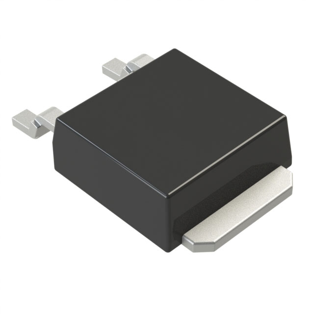
The RJK6002DPD-WS#J2 is an N-Channel MOSFET manufactured by Renesas Electronics Corporation, rated for 600V drain-to-source voltage with 2A continuous drain current at 25°C. This device is packaged in a surface mount MP-3A (TO-252-3 DPAK) configuration and is designed for 30W power dissipation applications. The part is classified as obsolete, making identification of functionally equivalent alternatives necessary for ongoing design support and procurement continuity.
Substiute Parts
Key Parameters
| Parameter | Value | Unit |
|---|---|---|
| FET Type | N-Channel | — |
| Drain-to-Source Voltage (Vdss) | 600 | V |
| Continuous Drain Current (Id) @ 25°C | 2 | A |
| Drive Voltage (Max Rds On) | 10 | V |
| Rds On (Max) @ Id, Vgs | 6.8 | Ohm @ 1A, 10V |
| Gate Threshold Voltage (Vgs(th)) (Max) | 4.5 | V @ 1mA |
| Power Dissipation (Max) | 30 | W (Tc) |
| Operating Temperature (Max) | 150 | °C |
| Package Type | TO-252-3, DPAK | — |
| Mounting Type | Surface Mount | — |
Substitute Part Grouping Explanation
Substitution of the RJK6002DPD-WS#J2 is determined by the following critical electrical and mechanical parameters:
Electrical Compatibility Criteria:
- Drain-to-Source Voltage (Vdss) must equal or exceed 600V
- Continuous Drain Current (Id) must meet or exceed 2A at 25°C
- Gate drive voltage compatibility at 10V
- On-state resistance (Rds On) characteristics within acceptable operating range
- Gate threshold voltage (Vgs(th)) within compatible range
- Maximum gate voltage (Vgs) rating of ±30V
- Power dissipation capability of 30W or greater
Mechanical Compatibility Criteria:
- Surface mount packaging in TO-252-3 DPAK configuration
- Identical pin configuration (2 Leads + Tab)
- Moisture Sensitivity Level 1 (Unlimited)
The IRFR1N60APBF meets these substitution criteria through equivalent voltage ratings, compatible package geometry, and surface mount configuration, despite variations in absolute current and power ratings.
Parameter Comparison
| Parameter | RJK6002DPD-WS#J2 | IRFR1N60APBF | Unit |
|---|---|---|---|
| Manufacturer | Renesas Electronics | Vishay Siliconix | — |
| FET Type | N-Channel | N-Channel | — |
| Drain-to-Source Voltage (Vdss) | 600 | 600 | V |
| Continuous Drain Current (Id) @ 25°C | 2 | 1.4 | A |
| Drive Voltage (Max Rds On) | 10 | 10 | V |
| Rds On (Max) @ Id, Vgs | 6.8 @ 1A, 10V | 7 @ 840mA, 10V | Ohm |
| Gate Threshold Voltage (Vgs(th)) (Max) | 4.5 @ 1mA | 4 @ 250µA | V |
| Gate Charge (Qg) (Max) @ Vgs | 6.2 @ 10V | 14 @ 10V | nC |
| Input Capacitance (Ciss) (Max) @ Vds | 165 @ 25V | 229 @ 25V | pF |
| Power Dissipation (Max) | 30 | 36 | W (Tc) |
| Operating Temperature (Max) | 150 | 150 | °C |
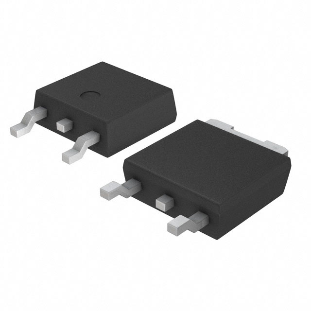
| Package Type | TO-252-3, DPAK | TO-252-3, DPAK | — |
| Mounting Type | Surface Mount | Surface Mount | — |
| Moisture Sensitivity Level | 1 (Unlimited) | 1 (Unlimited) | — |
| Product Status | Obsolete | Active | — |
Engineering Selection Recommendations
Primary Substitute: IRFR1N60APBF
The IRFR1N60APBF is the qualified substitute for the RJK6002DPD-WS#J2 based on the following factors:
-
Voltage Rating Equivalence: Both devices are rated for 600V Vdss, ensuring compatibility in high-voltage switching applications.
-
Package Compatibility: Both devices utilize the TO-252-3 DPAK surface mount package with identical pin configuration (2 Leads + Tab), enabling direct PCB layout compatibility without redesign.
-
Product Status: The IRFR1N60APBF is classified as Active, providing long-term availability and supply chain continuity compared to the obsolete RJK6002DPD-WS#J2.
-
Compliance Certifications: The IRFR1N60APBF carries RoHS3 compliance and REACH Affected status, meeting current regulatory requirements for electronic component procurement.
-
Thermal Characteristics: The IRFR1N60APBF provides 36W maximum power dissipation, exceeding the 30W requirement of the original part, offering improved thermal margin.
Design Considerations:
The IRFR1N60APBF exhibits a continuous drain current rating of 1.4A compared to the original 2A specification. Circuit designs operating at or near the 2A maximum must be evaluated to confirm operation within the substitute part's current rating. The increased gate charge (14 nC versus 6.2 nC) and input capacitance (229 pF versus 165 pF) may affect gate drive circuit timing and switching speed characteristics in high-frequency applications.
Frequently Asked Questions (FAQ)
Q: Can the IRFR1N60APBF directly replace the RJK6002DPD-WS#J2 without PCB modifications?
A: Yes. Both devices share identical TO-252-3 DPAK packaging with the same pin configuration (2 Leads + Tab), enabling direct footprint compatibility. No PCB layout changes are required for mechanical and electrical connection.
Q: What is the primary difference between these two devices?
A: The primary difference is the continuous drain current rating. The RJK6002DPD-WS#J2 is rated for 2A at 25°C, while the IRFR1N60APBF is rated for 1.4A at case temperature. Both maintain identical 600V voltage ratings and compatible on-state resistance characteristics at 10V gate drive.
Q: Are there any gate drive circuit modifications needed when substituting to the IRFR1N60APBF?
A: The gate threshold voltage (Vgs(th)) specifications are compatible (4.5V maximum for the original versus 4 maximum for the substitute). However, the IRFR1N60APBF exhibits higher gate charge (14 nC versus 6.2 nC) and input capacitance (229 pF versus 165 pF). Gate drive circuits with current-limited sources or high-impedance drivers may require evaluation to ensure adequate gate charge delivery within required switching time windows.
Q: Is the IRFR1N60APBF suitable for applications requiring the full 2A continuous current specification?
A: Applications requiring sustained operation at or above 1.4A continuous drain current must be re-evaluated using the IRFR1N60APBF specifications. The substitute part is rated for 1.4A maximum continuous drain current. Thermal analysis and duty cycle assessment are necessary to confirm suitability for specific current requirements.
Q: What compliance advantages does the IRFR1N60APBF offer over the obsolete RJK6002DPD-WS#J2?
A: The IRFR1N60APBF carries Active product status with RoHS3 compliance and REACH Affected designation, meeting current regulatory requirements for new designs and procurement. The RJK6002DPD-WS#J2 is classified as obsolete, limiting long-term availability and support.
Q: Are the maximum gate voltage ratings compatible between these devices?
A: Yes. Both devices are rated for ±30V maximum gate voltage (Vgs), ensuring compatibility with standard gate drive voltage levels used in switching applications.
Q: How do the power dissipation ratings compare?
A: The IRFR1N60APBF provides 36W maximum power dissipation at case temperature, compared to 30W for the RJK6002DPD-WS#J2. This represents a 20% increase in thermal capability, providing additional margin for thermal management in the substitute device.
Alternative Parts

SJ6012L2TP
Littelfuse Inc.
6 Alternative Parts

JMK107BBJ476MA-RE
Taiyo Yuden
10 Alternative Parts

GMK107BBJ475MA-T
Taiyo Yuden
5 Alternative Parts
SJ6020N2ARP
Littelfuse Inc.
3 Alternative Parts
SJ6025R2ATP
Littelfuse Inc.
4 Alternative Parts

2474-05L
API Delevan Inc.
1 Alternative Parts

4590R-684K
API Delevan Inc.
1 Alternative Parts

CM6560R-334
API Delevan Inc.
1 Alternative Parts

CM6460-104
API Delevan Inc.
1 Alternative Parts

5526-12
API Delevan Inc.
1 Alternative Parts