


Request Quote
(Ships tomorrow)
PZM6.2NB2,115 Equivalent & Substitute Parts Engineering Reference
Part Overview
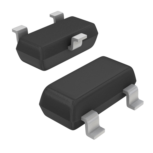
The NXP PZM6.2NB2,115 is a 6.2V zener diode in a surface-mount SMT3 (SOT-23-3) package, with a maximum power dissipation of 300mW and ±2% voltage tolerance. It is RoHS3 compliant, with an operating temperature range of -65°C to 150°C, maximum zener impedance of 10 Ohms, and forward voltage of 1.1V at 100mA. The part is marked obsolete, which makes the selection of equivalent or substitute models essential for ongoing engineering support and production continuity.
Substiute Parts
Key Parameters
| Parameter | PZM6.2NB2,115 |
|---|---|
| Voltage - Zener (Nom) (Vz) | 6.2 V |
| Tolerance | ±2% |
| Power - Max | 300 mW |
| Impedance (Max) (Zzt) | 10 Ohms |
| Current - Reverse Leakage @ Vr | 2 µA @ 3 V |
| Voltage - Forward (Vf) (Max) @ If | 1.1 V @ 100 mA |
| Operating Temperature | -65°C ~ 150°C |
| Mounting Type | Surface Mount |
| Package / Case | TO-236-3, SC-59, SOT-23-3 |
| RoHS Status | ROHS3 Compliant |
| Inventory Status | Obsolete |
Substitute Part Grouping Explanation
Substitute and equivalent parts for PZM6.2NB2,115 are selected strictly based on the following key parameters: zener voltage (6.2V, ±2%), maximum power rating (≥225mW), maximum zener impedance (≤10 Ohms), reverse leakage current (≤3µA at voltage conditions), forward voltage, identical SOT-23-3/TO-236-3 form factor for compatibility, and operating temperature range (-65°C to 150°C). All listed substitutes provide RoHS3 compliance, meet the noted moisture sensitivity and have matching mounting and packaging standards.
Parameter Comparison
| Part Number | Manufacturer | Voltage - Zener (Nom) (Vz) | Tolerance | Power - Max | Impedance (Max) (Zzt) | Current - Reverse Leakage @ Vr | Voltage - Forward (Vf) (Max) @ If | Operating Temperature | Mounting Type | Package / Case | RoHS Status | Inventory Status |
|---|---|---|---|---|---|---|---|---|---|---|---|---|
| PZM6.2NB2,115 | NXP USA Inc. | 6.2 V | ±2% | 300 mW | 10 Ohms | 2 µA @ 3 V | 1.1 V @ 100 mA | -65°C ~ 150°C | Surface Mount | TO-236-3, SC-59, SOT-23-3 | ROHS3 Compliant | Obsolete |
| BZX84-B6V2,215 | Nexperia USA Inc. | 6.2 V | ±2% | 250 mW | 10 Ohms | 3 µA @ 4 V | 900 mV @ 10 mA | -65°C ~ 150°C | Surface Mount | TO-236-3, SC-59, SOT-23-3 | ROHS3 Compliant | Active |
| BZX84B6V2-7-F | Diodes Incorporated | 6.2 V | ±2% | 300 mW | 10 Ohms | 3 µA @ 4 V | 900 mV @ 10 mA | -65°C ~ 150°C | Surface Mount | TO-236-3, SC-59, SOT-23-3 | ROHS3 Compliant | Active |
| SZBZX84B6V2LT1G | onsemi | 6.2 V | ±2% | 225 mW | 10 Ohms | 3 µA @ 4 V | 900 mV @ 10 mA | -65°C ~ 150°C (TJ) | Surface Mount | TO-236-3, SC-59, SOT-23-3 | ROHS3 Compliant | Active |
Engineering Selection Recommendations
Select substitute or equivalent parts for PZM6.2NB2,115 that carry current "Active" inventory status, are ROHS3 Compliant, meet the specified operating temperature range, and use the SOT-23-3/TO-236-3 package. Follow project requirements for environmental compliance and supply continuity. Substitute selection must strictly contain the part numbers listed in the comparison table with aligned specifications and certifications.
Frequently Asked Questions (FAQ)
Q1: What are the essential parameters for replacing PZM6.2NB2,115?
Only voltage - zener (nominal) 6.2V, ±2% tolerance, equivalent or higher power rating, maximum zener impedance, leakage current within stated limits, surface-mount SOT-23-3/TO-236-3 packaging, and environmental compliance.
Q2: Are the pinouts and footprints for the listed substitutes identical?
All substitute part numbers are in compatible packages (TO-236-3, SC-59, SOT-23-3), matching mounting type and layout standards with PZM6.2NB2,115.
Q3: Do the listed substitute zener diodes comply with RoHS?
All specified equivalents are ROHS3 Compliant.
Q4: How does the obsolete status of PZM6.2NB2,115 affect engineering selection?
Parts with "Obsolete" status require substitutes with "Active" status and aligned electrical, mechanical, and compliance parameters for continued design support.
Q5: What are the permitted differences for power dissipation in substitutes?
Power rating must be equal to or greater than the minimum required by the circuit application, with listed substitutes ranging from 225 mW to 300 mW as specified.
Alternative Parts

SJ6012L2TP
Littelfuse Inc.
6 Alternative Parts

JMK107BBJ476MA-RE
Taiyo Yuden
10 Alternative Parts

GMK107BBJ475MA-T
Taiyo Yuden
5 Alternative Parts
SJ6020N2ARP
Littelfuse Inc.
3 Alternative Parts
SJ6025R2ATP
Littelfuse Inc.
4 Alternative Parts

2474-05L
API Delevan Inc.
1 Alternative Parts

4590R-684K
API Delevan Inc.
1 Alternative Parts

CM6560R-334
API Delevan Inc.
1 Alternative Parts

CM6460-104
API Delevan Inc.
1 Alternative Parts

5526-12
API Delevan Inc.
1 Alternative Parts