


Request Quote
(Ships tomorrow)
PVC6M104A01B00 Equivalent & Substitute Parts
Part Overview
The PVC6M104A01B00 is a 100 kOhms, 0.5W through-hole trimmer potentiometer manufactured by Bourns Inc. with ceramic resistive material, top adjustment, and PC pin termination. This part is classified as obsolete, making equivalent substitutes necessary for ongoing production and maintenance applications. Substitute parts maintain the core electrical specifications while offering improved availability and compliance status through active product lines.
Substiute Parts
Key Parameters
| Parameter | Value |
|---|---|
| Resistance | 100 kOhms |
| Power Rating | 0.5W (1/2W) |
| Tolerance | ±10% |
| Temperature Coefficient | ±100ppm/°C |
| Number of Turns | 1 |
| Adjustment Type | Top Adjustment |
| Mounting Type | Through Hole |
| Termination Style | PC Pins |
| Resistive Material | Ceramic |
Substitute Part Grouping Explanation
Substitution eligibility is determined by matching the following critical parameters: resistance value (100 kOhms), power rating (0.5W), tolerance (±10%), temperature coefficient (±100ppm/°C), number of turns (1), adjustment type (top adjustment), mounting type (through hole), and termination style (PC pins). All listed substitute parts meet these core electrical and mechanical requirements. Physical dimensions vary across substitute options, requiring mechanical fit verification during integration. Resistive material differs between the original ceramic design and substitute cermet designs, which do not affect electrical performance within the specified tolerance and temperature coefficient ranges.
Parameter Comparison
| Part Number | Manufacturer | Series | Resistance | Power (W) | Tolerance | Temp Coeff (ppm/°C) | Turns | Resistive Material | Size / Dimension | Product Status | RoHS Status |
|---|---|---|---|---|---|---|---|---|---|---|---|
| PVC6M104A01B00 | Bourns Inc. | PVC6 | 100 kOhms | 0.5 | ±10% | ±100 | 1 | Ceramic | Square - 0.272" x 0.272" (6.90mm x 6.90mm) | Obsolete | Non-compliant |
| 3362U-1-104LF | Bourns Inc. | Trimpot® 3362 - Sealed | 100 kOhms | 0.5 | ±10% | ±100 | 1 | Cermet | Rectangular - 0.275" x 0.260" (6.99mm x 6.60mm) | Active | ROHS3 Compliant |
| 25PR100KLF | TT Electronics / BI Technologies | 25 | 100 kOhms | 0.5 | ±10% | ±100 | 1 | Cermet | Square - 0.270" x 0.270" (6.86mm x 6.86mm) | Active | RoHS Compliant |
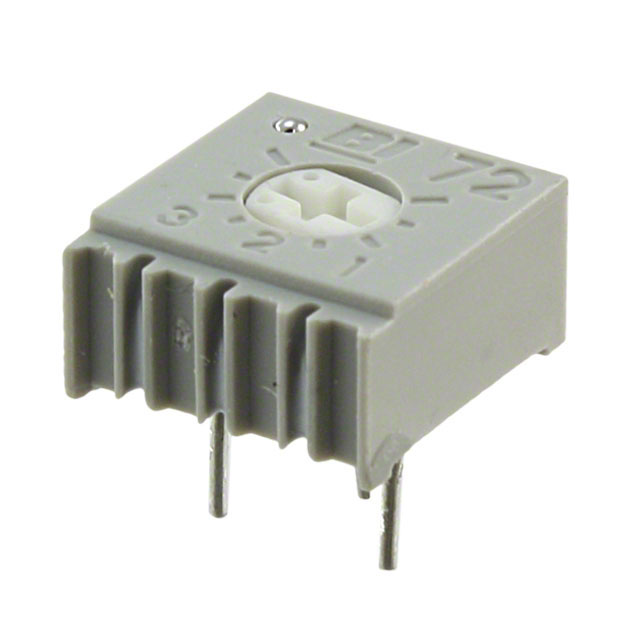
| 72PR100KLF | TT Electronics/BI | 72 | 100 kOhms | 0.5 | ±10% | ±100 | 1 | Cermet | Square - 0.375" x 0.375" (9.53mm x 9.53mm) | Active | ROHS3 Compliant |
| 72PMR100KLF | TT Electronics/BI | 72 | 100 kOhms | 0.5 | ±10% | ±100 | 1 | Cermet | Square - 0.375" x 0.375" (9.53mm x 9.53mm) | Active | ROHS3 Compliant |
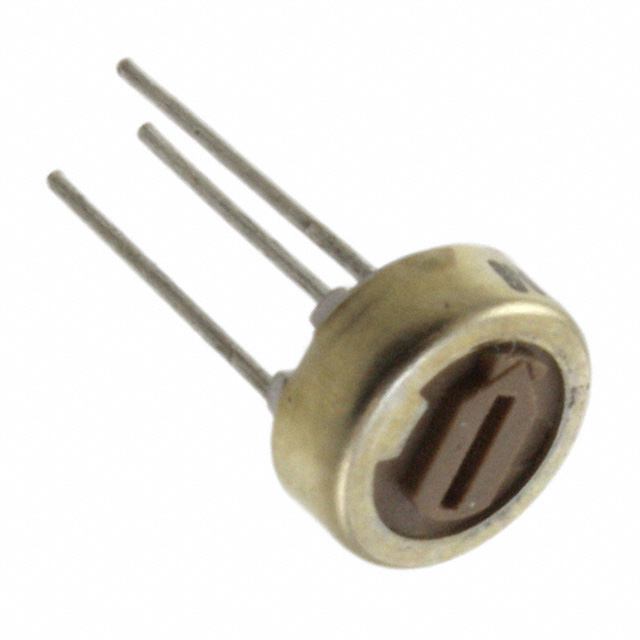
| 82PR100KLF | TT Electronics/BI | 82 | 100 kOhms | 0.5 | ±10% | ±100 | 1 | Cermet | Round - 0.250" Dia (6.35mm) | Active | ROHS3 Compliant |
Engineering Selection Recommendations
The 3362U-1-104LF from Bourns Inc. provides the closest dimensional compatibility with the original PVC6M104A01B00, maintaining similar footprint dimensions while offering active product status and ROHS3 compliance. This part is the primary direct substitute for applications requiring minimal PCB layout modifications.
The 25PR100KLF from TT Electronics / BI Technologies offers comparable dimensions to the original part with active status and RoHS compliance, suitable for applications where Bourns sourcing is not required.
The 72PR100KLF and 72PMR100KLF from TT Electronics/BI provide larger form factors (0.375" x 0.375") with active status and ROHS3 compliance. These parts are suitable for applications with available PCB space and where the larger footprint does not present mechanical constraints.
The 82PR100KLF from TT Electronics/BI features a round 0.250" diameter form factor with active status and ROHS3 compliance, applicable to designs requiring circular mounting profiles.
All substitute parts maintain electrical equivalence within the specified tolerance and temperature coefficient parameters. Physical dimensions and packaging formats must be evaluated against specific PCB layout and assembly requirements.
Frequently Asked Questions (FAQ)
Q: Can the PVC6M104A01B00 be directly replaced with any of the listed substitutes?
A: All listed substitute parts meet the core electrical specifications (100 kOhms, 0.5W, ±10% tolerance, ±100ppm/°C temperature coefficient, 1 turn, top adjustment, through-hole mounting, PC pin termination). Physical dimensions vary and must be verified against PCB layout constraints before implementation.
Q: What is the primary difference between the original ceramic design and the cermet substitute designs?
A: The original PVC6M104A01B00 uses ceramic resistive material, while all substitute parts use cermet resistive material. Both materials meet the specified electrical parameters and tolerance requirements. Cermet designs are commonly used in active product lines due to improved reliability and environmental compliance.
Q: Which substitute offers the best dimensional compatibility?
A: The 3362U-1-104LF provides the closest dimensional match with a rectangular footprint of 0.275" x 0.260" compared to the original 0.272" x 0.272" square footprint. The 25PR100KLF also offers similar dimensions at 0.270" x 0.270".
Q: Are all substitutes RoHS compliant?
A: The original PVC6M104A01B00 is RoHS non-compliant. The 3362U-1-104LF, 72PR100KLF, 72PMR100KLF, and 82PR100KLF are ROHS3 compliant. The 25PR100KLF is RoHS compliant. Compliance requirements should be verified against application standards.
Q: What packaging formats are available for the substitutes?
A: The 3362U-1-104LF is supplied in tube packaging. The 25PR100KLF is supplied in tube packaging. The 72PR100KLF, 72PMR100KLF, and 82PR100KLF are supplied in bulk packaging. Packaging selection depends on production volume and assembly process requirements.
Q: Can substitutes be used interchangeably in existing designs?
A: Electrical interchangeability is confirmed for all listed parts. Mechanical interchangeability requires verification of PCB footprint, mounting hole spacing, and available board space. Form factor differences (square, rectangular, or round) may necessitate PCB layout modifications.
Alternative Parts

SJ6012L2TP
Littelfuse Inc.
6 Alternative Parts

JMK107BBJ476MA-RE
Taiyo Yuden
10 Alternative Parts

GMK107BBJ475MA-T
Taiyo Yuden
5 Alternative Parts
SJ6020N2ARP
Littelfuse Inc.
3 Alternative Parts
SJ6025R2ATP
Littelfuse Inc.
4 Alternative Parts

2474-05L
API Delevan Inc.
1 Alternative Parts

4590R-684K
API Delevan Inc.
1 Alternative Parts

CM6560R-334
API Delevan Inc.
1 Alternative Parts

CM6460-104
API Delevan Inc.
1 Alternative Parts

5526-12
API Delevan Inc.
1 Alternative Parts