


Request Quote
(Ships tomorrow)
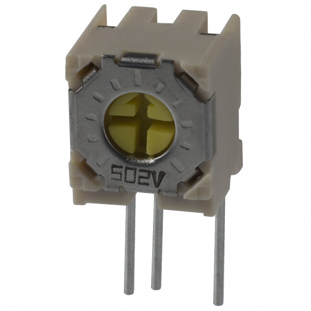
PVC6H504C01B00 Equivalent & Substitute Parts
Part Overview
The PVC6H504C01B00 is a 500 kOhms, 0.5W through-hole trimmer potentiometer manufactured by Bourns Inc. with ceramic resistive material, side adjustment, and PC pin termination. This part is classified as obsolete, making identification of suitable substitutes necessary for ongoing design support and component procurement.
Substiute Parts
Key Parameters
| Parameter | Value |
|---|---|
| Resistance | 500 kOhms |
| Power Rating | 0.5W (1/2W) |
| Tolerance | ±10% |
| Temperature Coefficient | ±100ppm/°C |
| Number of Turns | 1.0 Turn |
| Adjustment Type | Side Adjustment |
| Mounting Type | Through Hole |
| Termination Style | PC Pins |
| Face Dimension | Rectangular - 0.315" x 0.272" (8.00mm x 6.90mm) |
| RoHS Status | ROHS3 Compliant |
Substitute Part Grouping Explanation
The 3362X-1-504LF qualifies as a direct substitute for the PVC6H504C01B00 based on the following critical parameters:
- Identical resistance value: 500 kOhms
- Matching power rating: 0.5W (1/2W)
- Identical tolerance: ±10%
- Identical temperature coefficient: ±100ppm/°C
- Identical number of turns: 1.0
- Identical adjustment type: Side Adjustment
- Identical mounting type: Through Hole
- Identical termination style: PC Pins
- RoHS3 compliance maintained
The primary difference is the resistive material composition (ceramic versus cermet) and a minor reduction in face dimensions (0.275" x 0.260" versus 0.315" x 0.272"). Both materials meet the specified electrical performance requirements.
Parameter Comparison
| Parameter | PVC6H504C01B00 | 3362X-1-504LF |
|---|---|---|
| Manufacturer | Bourns Inc. | Bourns Inc. |
| Resistance | 500 kOhms | 500 kOhms |
| Power Rating | 0.5W | 0.5W |
| Tolerance | ±10% | ±10% |
| Temperature Coefficient | ±100ppm/°C | ±100ppm/°C |
| Number of Turns | 1.0 | 1.0 |
| Adjustment Type | Side Adjustment | Side Adjustment |
| Resistive Material | Ceramic | Cermet |
| Mounting Type | Through Hole | Through Hole |
| Termination Style | PC Pins | PC Pins |
| Face Dimension | 0.315" x 0.272" (8.00mm x 6.90mm) | 0.275" x 0.260" (6.99mm x 6.60mm) |
| Product Status | Obsolete | Active |
| RoHS Status | ROHS3 Compliant | ROHS3 Compliant |
Engineering Selection Recommendations
The 3362X-1-504LF is the qualified substitute for the obsolete PVC6H504C01B00. Both parts maintain ROHS3 compliance and are manufactured by Bourns Inc. The substitute part carries active product status, ensuring long-term availability and supply chain continuity.
The cermet resistive material in the 3362X-1-504LF provides equivalent electrical performance to the ceramic material in the original part across the specified tolerance and temperature coefficient ranges. The reduced face dimensions of the substitute part require verification of mechanical fit within the PCB layout and enclosure constraints of the original design.
Frequently Asked Questions (FAQ)
Q: Can the 3362X-1-504LF be used as a direct replacement for the PVC6H504C01B00?
A: Yes. Both parts share identical electrical specifications: 500 kOhms resistance, 0.5W power rating, ±10% tolerance, ±100ppm/°C temperature coefficient, 1.0 turn adjustment, side adjustment type, through-hole mounting, and PC pin termination. Mechanical fit must be confirmed due to the smaller face dimensions of the substitute.
Q: What is the difference between ceramic and cermet resistive materials in this application?
A: Both materials meet the specified electrical performance parameters. Cermet (ceramic-metal composite) offers enhanced stability and reliability in sealed designs, as indicated by the Trimpot® 3362 series classification of the substitute part.
Q: Are there any compliance differences between these parts?
A: Both parts are ROHS3 compliant. The substitute part is REACH Affected, whereas the original part is REACH Unaffected. Compliance requirements should be verified against applicable regulations for the end application.
Q: What packaging is available for the substitute part?
A: The 3362X-1-504LF is supplied in Tube packaging, compared to the original part's standard packaging designation.
Q: Should PCB layout be modified to accommodate the substitute part?
A: The substitute part has reduced face dimensions (0.275" x 0.260" versus 0.315" x 0.272"). Existing PCB layouts designed for the original part will accommodate the smaller substitute without modification. However, mechanical clearance and mounting hole alignment must be verified.
Alternative Parts

SJ6012L2TP
Littelfuse Inc.
6 Alternative Parts

JMK107BBJ476MA-RE
Taiyo Yuden
10 Alternative Parts

GMK107BBJ475MA-T
Taiyo Yuden
5 Alternative Parts
SJ6020N2ARP
Littelfuse Inc.
3 Alternative Parts
SJ6025R2ATP
Littelfuse Inc.
4 Alternative Parts

2474-05L
API Delevan Inc.
1 Alternative Parts

4590R-684K
API Delevan Inc.
1 Alternative Parts

CM6560R-334
API Delevan Inc.
1 Alternative Parts

CM6460-104
API Delevan Inc.
1 Alternative Parts

5526-12
API Delevan Inc.
1 Alternative Parts