


Request Quote
(Ships tomorrow)
PUMH30,115 Pre-Biased Dual NPN Transistor Equivalent & Substitute Parts
Part Overview
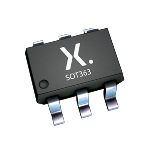
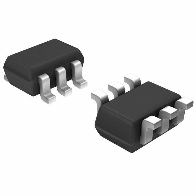
The PUMH30,115 is an active pre-biased dual NPN transistor manufactured by Nexperia USA Inc., designed for surface mount applications in the 6-TSSOP package. This component integrates two NPN transistors with internal biasing resistors, rated for 50V collector-emitter breakdown voltage and 100mA maximum collector current. The part is AEC-Q100 qualified for automotive applications and RoHS3 compliant.
Substitute parts are identified when equivalent electrical performance can be achieved within the specified parameter ranges while maintaining the same package form factor and functional configuration.
Substiute Parts
Key Parameters
| Parameter | Value | Unit |
|---|---|---|
| Transistor Type | 2 NPN - Pre-Biased (Dual) | — |
| Current - Collector (Ic) Max | 100 | mA |
| Voltage - Collector Emitter Breakdown (Max) | 50 | V |
| Resistor - Base (R1) | 2.2 | kOhms |
| Power - Max | 300 | mW |
| Package / Case | 6-TSSOP, SC-88, SOT-363 | — |
| Mounting Type | Surface Mount | — |
| RoHS Status | ROHS3 Compliant | — |
| Grade | Automotive | — |
| Qualification | AEC-Q100 | — |
Substitute Part Grouping Explanation
Substitution eligibility for the PUMH30,115 is determined by the following criteria:
Mandatory Matching Parameters:
- Transistor configuration: 2 NPN - Pre-Biased (Dual)
- Maximum collector current: 100mA
- Collector-emitter breakdown voltage: 50V
- Package form factor: 6-TSSOP / SC-88 / SOT-363
- Mounting type: Surface Mount
- RoHS3 compliance
Allowable Variation Parameters:
- Base resistor (R1) value: Varies by part design (2.2kOhms, 4.7kOhms, 10kOhms, 47kOhms)
- DC current gain (hFE): Varies by part design and measurement conditions
- Vce saturation: Varies by part design
- Power dissipation: Substitute parts rated at 150mW or higher
- Frequency - Transition: Substitute parts with 250MHz specification exceed baseline performance
All identified substitute parts meet the mandatory matching criteria and are manufactured by Rohm Semiconductor with equivalent active product status and RoHS3 compliance.
Parameter Comparison
| Parameter | PUMH30,115 (Nexperia) | UMH10NTN (Rohm) | UMH11NTN (Rohm) | UMH2NTN (Rohm) | UMH3NTN (Rohm) | UMH9NTN (Rohm) |
|---|---|---|---|---|---|---|
| Transistor Type | 2 NPN - Pre-Biased (Dual) | 2 NPN - Pre-Biased (Dual) | 2 NPN - Pre-Biased (Dual) | 2 NPN - Pre-Biased (Dual) | 2 NPN - Pre-Biased (Dual) | 2 NPN - Pre-Biased (Dual) |
| Current - Collector (Ic) Max | 100 | 100 | 100 | 100 | 100 | 100 |
| Voltage - Collector Emitter Breakdown (Max) | 50 | 50 | 50 | 50 | 50 | 50 |
| Resistor - Base (R1) | 2.2k | 2.2k | 10k | 47k | 4.7k | 10k |
| Resistor - Emitter Base (R2) | — | 47k | 10k | 47k | — | 47k |
| DC Current Gain (hFE) Min @ Ic, Vce | 30 @ 20mA, 5V | 80 @ 10mA, 5V | 30 @ 5mA, 5V | 68 @ 5mA, 5V | 100 @ 1mA, 5V | 68 @ 5mA, 5V |
| Vce Saturation (Max) @ Ib, Ic | 150mV @ 500µA, 10mA | 300mV @ 250µA, 5mA | 300mV @ 500µA, 10mA | 300mV @ 500µA, 10mA | 300mV @ 250µA, 5mA | 300mV @ 250µA, 5mA |
| Current - Collector Cutoff (Max) | 1µA | 500nA | 500nA | 500nA | — | 500nA |
| Frequency - Transition | — | 250MHz | 250MHz | 250MHz | 250MHz | 250MHz |
| Power - Max | 300 | 150 | 150 | 150 | 150 | 150 |
| Package / Case | 6-TSSOP, SC-88, SOT-363 | 6-TSSOP, SC-88, SOT-363 | 6-TSSOP, SC-88, SOT-363 | 6-TSSOP, SC-88, SOT-363 | 6-TSSOP, SC-88, SOT-363 | 6-TSSOP, SC-88, SOT-363 |
| RoHS Status | ROHS3 Compliant | ROHS3 Compliant | ROHS3 Compliant | ROHS3 Compliant | ROHS3 Compliant | ROHS3 Compliant |
| Moisture Sensitivity Level (MSL) | 1 (Unlimited) | 1 (Unlimited) | 1 (Unlimited) | 1 (Unlimited) | 1 (Unlimited) | 1 (Unlimited) |
| Product Status | Active | Active | Active | Active | Active | Active |
Engineering Selection Recommendations
All identified substitute parts (UMH10NTN, UMH11NTN, UMH2NTN, UMH3NTN, UMH9NTN) are active products manufactured by Rohm Semiconductor with RoHS3 compliance and MSL Level 1 rating, matching the environmental and regulatory requirements of the PUMH30,115.
Selection Basis by Application:
UMH10NTN — Suitable for applications requiring R1 = 2.2kOhms matching the PUMH30,115 base resistor value. Provides 80mA hFE minimum at 10mA collector current with 250MHz transition frequency.
UMH11NTN — Suitable for applications with symmetric biasing resistor configuration (R1 = R2 = 10kOhms). Provides 30mA hFE minimum at 5mA collector current, matching the PUMH30,115 hFE specification at different measurement conditions.
UMH2NTN — Suitable for high-impedance biasing applications with R1 = R2 = 47kOhms. Provides 68mA hFE minimum at 5mA collector current.
UMH3NTN — Suitable for applications requiring R1 = 4.7kOhms with no emitter-base resistor. Provides highest hFE minimum (100mA) at 1mA collector current.
UMH9NTN — Suitable for applications with mixed biasing resistor configuration (R1 = 10kOhms, R2 = 47kOhms). Provides 68mA hFE minimum at 5mA collector current with 250MHz transition frequency.
All substitute parts operate within the 50V collector-emitter breakdown voltage and 100mA maximum collector current specifications. Power dissipation in substitute parts is rated at 150mW, which is lower than the PUMH30,115 (300mW) and must be considered in thermal design calculations for high-power applications.
Frequently Asked Questions (FAQ)
Q: Can UMH series parts directly replace PUMH30,115 in existing designs?
A: UMH series parts are electrically compatible within the specified parameter ranges and use the same 6-TSSOP package. However, the internal biasing resistor values differ across the UMH product line. Selection must be based on the specific biasing resistor requirements of the circuit design. Verify that the chosen UMH variant matches the intended base and emitter-base resistor values for your application.
Q: What is the significance of the different R1 and R2 resistor values in the substitute parts?
A: The internal biasing resistors (R1 and R2) determine the quiescent base current and switching characteristics of the pre-biased transistor. Different resistor values produce different DC current gain (hFE) characteristics and saturation voltages. Selection of the correct resistor configuration is critical for proper circuit operation. The PUMH30,115 uses R1 = 2.2kOhms; UMH10NTN provides the closest match with identical R1 value.
Q: Why do substitute parts have lower maximum power dissipation (150mW vs. 300mW)?
A: The PUMH30,115 is rated for 300mW maximum power dissipation, while all Rohm UMH series substitutes are rated at 150mW. This difference reflects different thermal design specifications between manufacturers. In applications approaching the 300mW limit, thermal management and power dissipation calculations must be re-evaluated for the substitute part to ensure safe operation within the lower power rating.
Q: Are all substitute parts suitable for automotive applications?
A: The PUMH30,115 carries AEC-Q100 automotive qualification. The identified Rohm UMH series substitutes are active products with RoHS3 compliance and MSL Level 1 rating. However, the provided data does not specify AEC-Q100 qualification for the UMH parts. For automotive applications requiring AEC-Q100 certification, verify qualification status with the manufacturer before design implementation.
Q: What is the impact of the 250MHz transition frequency in substitute parts?
A: The PUMH30,115 does not specify a transition frequency. All UMH series substitutes are rated at 250MHz transition frequency, indicating higher-speed switching capability. This specification does not limit substitution; it indicates that UMH parts support higher-frequency operation than the baseline PUMH30,115 specification.
Q: How do the different hFE specifications affect circuit design?
A: DC current gain (hFE) varies across the substitute parts and is measured at different collector current and voltage conditions. UMH3NTN provides the highest hFE minimum (100mA @ 1mA, 5V), while UMH11NTN matches the PUMH30,115 hFE specification (30mA) at different measurement conditions. Circuit designs relying on specific hFE values must account for these variations in biasing calculations and gain stability analysis.
Q: Can substitute parts be used interchangeably in the same PCB assembly?
A: All substitute parts use the same 6-TSSOP package footprint and are compatible with existing PCB layouts. However, they cannot be used interchangeably without circuit analysis due to different internal biasing resistor configurations. Each UMH variant must be selected based on the specific biasing resistor requirements of the circuit design. Mixing different UMH variants in the same design is not recommended unless circuit topology supports multiple biasing configurations.
Alternative Parts

SJ6012L2TP
Littelfuse Inc.
6 Alternative Parts

JMK107BBJ476MA-RE
Taiyo Yuden
10 Alternative Parts

GMK107BBJ475MA-T
Taiyo Yuden
5 Alternative Parts
SJ6020N2ARP
Littelfuse Inc.
3 Alternative Parts
SJ6025R2ATP
Littelfuse Inc.
4 Alternative Parts

2474-05L
API Delevan Inc.
1 Alternative Parts

4590R-684K
API Delevan Inc.
1 Alternative Parts

CM6560R-334
API Delevan Inc.
1 Alternative Parts

CM6460-104
API Delevan Inc.
1 Alternative Parts

5526-12
API Delevan Inc.
1 Alternative Parts