


Request Quote
(Ships tomorrow)
PUMH15,115 Pre-Biased Bipolar Transistor Equivalent & Substitute Parts
Part Overview
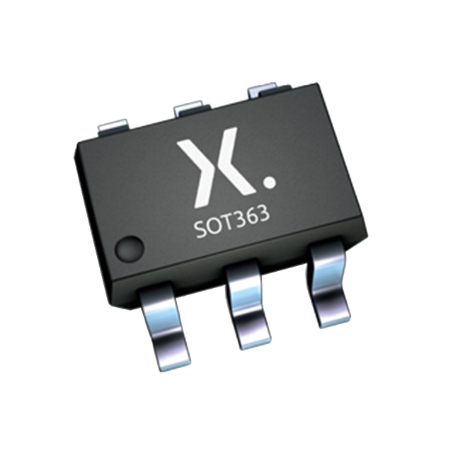
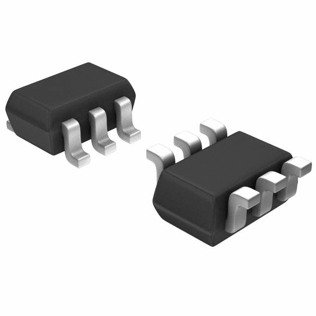
The PUMH15,115 is an active pre-biased dual NPN bipolar transistor (BJT) manufactured by Nexperia USA Inc. in a 6-TSSOP surface mount package. This component integrates two NPN transistors with internal biasing resistors, designed for applications requiring compact switching and amplification circuits with 50V collector-emitter breakdown voltage and 100mA maximum collector current. The part is AEC-Q100 qualified for automotive applications and RoHS3 compliant. Equivalent and substitute parts are identified based on matching electrical specifications, package compatibility, and functional characteristics to support design flexibility and supply chain continuity.
Substiute Parts
Key Parameters
| Parameter | Value | Unit |
|---|---|---|
| Transistor Type | 2 NPN - Pre-Biased (Dual) | — |
| Current - Collector (Ic) (Max) | 100 | mA |
| Voltage - Collector Emitter Breakdown (Max) | 50 | V |
| Resistor - Base (R1) | 4.7 | kOhms |
| Resistor - Emitter Base (R2) | 4.7 | kOhms |
| DC Current Gain (hFE) (Min) @ Ic, Vce | 30 @ 10mA, 5V | — |
| Vce Saturation (Max) @ Ib, Ic | 150 | mV @ 500µA, 10mA |
| Current - Collector Cutoff (Max) | 1 | µA |
| Power - Max | 300 | mW |
| Package / Case | 6-TSSOP, SC-88, SOT-363 | — |
| Mounting Type | Surface Mount | — |
| RoHS Status | ROHS3 Compliant | — |
| Grade | Automotive | — |
| Qualification | AEC-Q100 | — |
Substitute Part Grouping Explanation
Substitute parts for the PUMH15,115 are selected based on the following critical parameters that determine functional equivalence:
Primary Matching Criteria:
- Maximum collector current (Ic): 100mA
- Collector-emitter breakdown voltage (Vce(br)): 50V
- Base resistor (R1): 4.7kOhms
- Emitter-base resistor (R2): 4.7kOhms (or compatible value)
- Surface mount package compatibility: 6-TSSOP, SC-88, SOT-363
- RoHS3 compliance and MSL Level 1
Substitution Categories:
Category 1: Direct Dual NPN Pre-Biased Equivalents Parts with identical transistor configuration (2 NPN), matching resistor values, and equivalent electrical performance. These parts are fully interchangeable in applications where the specific transistor type configuration is required.
Category 2: Complementary Pre-Biased Equivalents Parts with mixed transistor configuration (1 NPN, 1 PNP) that share the same voltage and current ratings, resistor values, and package footprint. These parts are suitable for applications where complementary transistor pairs provide functional advantages.
Category 3: Compatible Variants Parts with minor parameter variations in saturation voltage, cutoff current, or transition frequency that remain within acceptable operating ranges for the application while maintaining package and voltage/current compatibility.
Parameter Comparison
| Parameter | PUMH15,115 (Nexperia) | MUN5232DW1T1G (onsemi) | RN1901,LF(CT (Toshiba) | RN4901,LF(CT (Toshiba) | DCX143EU-7-F (Diodes Inc.) |
|---|---|---|---|---|---|
| Manufacturer | Nexperia USA Inc. | onsemi | Toshiba Semiconductor | Toshiba Semiconductor | Diodes Incorporated |
| Transistor Type | 2 NPN - Pre-Biased | 2 NPN - Pre-Biased | 2 NPN - Pre-Biased | 1 NPN, 1 PNP - Pre-Biased | 1 NPN, 1 PNP - Pre-Biased |
| Ic (Max) | 100 mA | 100 mA | 100 mA | 100 mA | 100 mA |
| Vce(br) (Max) | 50 V | 50 V | 50 V | 50 V | 50 V |
| R1 (Base) | 4.7 kOhms | 4.7 kOhms | 4.7 kOhms | 4.7 kOhms | 4.7 kOhms |
| R2 (Emitter-Base) | 4.7 kOhms | 4.7 kOhms | 1 kOhms | 4.7 kOhms | 4.7 kOhms |
| hFE (Min) @ Ic, Vce | 30 @ 10mA, 5V | 15 @ 5mA, 10V | 30 @ 10mA, 5V | 30 @ 10mA, 5V | 50 @ 10mA, 5V / 40 @ 10mA, 5V |
| Vce Saturation (Max) | 150 mV @ 500µA, 10mA | 250 mV @ 1mA, 10mA | 300 mV @ 250µA, 5mA | 300 mV @ 250µA, 5mA | 300 mV @ 500µA, 10mA |
| Icbo (Max) | 1 µA | 500 nA | 100 nA | 500 nA | 500 nA |
| Frequency - Transition | — (Not specified) | — (Not specified) | 250 MHz | 250 MHz, 200 MHz | 250 MHz |
| Power - Max | 300 mW | 250 mW | 200 mW | 200 mW | 200 mW |
| Package | 6-TSSOP, SC-88, SOT-363 | SC-88/SC70-6/SOT-363 | US6 | US6 | SOT-363 |
| RoHS Status | ROHS3 Compliant | ROHS3 Compliant | ROHS3 Compliant | ROHS3 Compliant | ROHS3 Compliant |
| MSL | 1 (Unlimited) | 1 (Unlimited) | 1 (Unlimited) | 1 (Unlimited) | 1 (Unlimited) |
Engineering Selection Recommendations
MUN5232DW1T1G (onsemi) - Dual NPN Pre-Biased
This part is a direct functional equivalent with identical transistor configuration (2 NPN), matching voltage and current ratings, and compatible resistor values. The MUN5232DW1T1G maintains RoHS3 compliance and MSL Level 1 rating. The primary difference is lower maximum power dissipation (250mW vs. 300mW) and lower hFE specification (15 @ 5mA, 10V). Selection is appropriate for applications where the lower power rating is acceptable and the lower hFE does not impact circuit performance. Inventory availability is high (24,100 pcs).
RN1901,LF(CT (Toshiba) - Dual NPN Pre-Biased
This part provides dual NPN pre-biased configuration with matching voltage and current specifications. The RN1901 features transition frequency of 250MHz and lower power rating (200mW). The emitter-base resistor (R2) differs at 1kOhm versus 4.7kOhm, which affects biasing characteristics. The lower Icbo (100nA) provides superior leakage performance. Selection is appropriate where higher frequency response and lower leakage are beneficial, provided the different R2 value is compatible with circuit requirements. RoHS3 and MSL Level 1 compliant.
RN4901,LF(CT (Toshiba) - Complementary Pre-Biased
This part provides complementary NPN/PNP configuration with matching voltage and current ratings and identical resistor values (4.7kOhm/4.7kOhm). The RN4901 features dual transition frequencies (250MHz, 200MHz) and lower power rating (200mW). Selection is appropriate for applications requiring complementary transistor pairs within the same package, such as push-pull output stages or complementary switching circuits. RoHS3 and MSL Level 1 compliant.
DCX143EU-7-F (Diodes Incorporated) - Complementary Pre-Biased
This part provides complementary NPN/PNP configuration with matching voltage and current ratings and identical resistor values. The DCX143 features transition frequency of 250MHz and lower power rating (200mW). The hFE specification is higher (50/40 @ 10mA, 5V) and Icbo is lower (500nA). Selection is appropriate for applications requiring complementary transistor pairs where higher current gain is beneficial. RoHS3 and MSL Level 1 compliant.
Automotive and Compliance Considerations
The PUMH15,115 carries AEC-Q100 automotive qualification. Substitute parts from onsemi, Toshiba, and Diodes Incorporated are all RoHS3 compliant and MSL Level 1 rated. For automotive applications requiring AEC-Q100 qualification, verification of the substitute part's automotive qualification status is necessary based on specific application requirements and design standards.
Frequently Asked Questions (FAQ)
Q: Can the MUN5232DW1T1G replace the PUMH15,115 in all applications?
A: The MUN5232DW1T1G is a direct dual NPN equivalent with matching voltage, current, and resistor specifications. The primary differences are lower maximum power dissipation (250mW vs. 300mW) and lower hFE (15 @ 5mA, 10V vs. 30 @ 10mA, 5V). Substitution is valid for applications where the lower power rating and hFE specification do not exceed circuit requirements.
Q: What is the difference between the dual NPN parts (MUN5232DW1T1G, RN1901,LF(CT) and the complementary parts (RN4901,LF(CT, DCX143EU-7-F)?
A: Dual NPN parts contain two NPN transistors with internal biasing resistors. Complementary parts contain one NPN and one PNP transistor. Dual NPN parts are suitable for applications requiring two independent NPN switching or amplification stages. Complementary parts are designed for applications such as push-pull output stages, complementary switching circuits, or applications requiring both NPN and PNP functionality within a single package.
Q: Are all substitute parts compatible with the 6-TSSOP package footprint?
A: The PUMH15,115 is specified in 6-TSSOP, SC-88, and SOT-363 packages. The MUN5232DW1T1G is specified in SC-88/SC70-6/SOT-363. The RN1901,LF(CT and RN4901,LF(CT are specified in US6 package. The DCX143EU-7-F is specified in SOT-363. Physical package compatibility must be verified against the specific supplier device package designation. SOT-363 and SC-88 are mechanically equivalent, but US6 and 6-TSSOP may differ in pin configuration and footprint.
Q: What is the impact of different R2 (emitter-base resistor) values on substitution?
A: The PUMH15,115 has R2 = 4.7kOhms. The RN1901,LF(CT has R2 = 1kOhm. The emitter-base resistor affects the biasing network and switching characteristics. A lower R2 value (1kOhm) provides stronger base-emitter biasing, potentially resulting in faster switching and lower saturation voltage. Substitution with different R2 values is valid only if circuit analysis confirms the biasing change does not degrade performance.
Q: Are all substitute parts RoHS3 compliant and MSL Level 1?
A: All identified substitute parts (MUN5232DW1T1G, RN1901,LF(CT, RN4901,LF(CT, DCX143EU-7-F) are RoHS3 compliant and MSL Level 1 rated, matching the PUMH15,115 environmental and handling specifications.
Q: What is the significance of transition frequency (fT) specifications?
A: Transition frequency indicates the frequency at which current gain drops to unity. The PUMH15,115 does not specify transition frequency. The RN1901,LF(CT, RN4901,LF(CT, and DCX143EU-7-F specify 250MHz transition frequency. Higher transition frequency indicates better high-frequency performance. For applications operating at frequencies below the specified fT, the difference is not significant. For high-frequency applications, parts with specified fT provide documented frequency response.
Q: How do differences in Vce saturation voltage affect circuit performance?
A: The PUMH15,115 specifies Vce saturation of 150mV @ 500µA, 10mA. Substitute parts range from 250mV to 300mV. Lower saturation voltage indicates better switching efficiency and lower power dissipation in saturated switching applications. Higher saturation voltage results in slightly higher power loss. For applications where saturation voltage is critical, the PUMH15,115 provides superior performance. Substitute parts with higher saturation voltage are acceptable for applications with less stringent efficiency requirements.
Q: What is the significance of Icbo (collector-base cutoff current) specifications?
A: The PUMH15,115 specifies Icbo of 1µA. Substitute parts specify 100nA to 500nA. Lower Icbo indicates lower leakage current and better high-temperature stability. For applications sensitive to leakage current or operating at elevated temperatures, parts with lower Icbo (RN1901,LF(CT at 100nA) provide superior performance. For general-purpose applications, the difference is not significant.
Alternative Parts

SJ6012L2TP
Littelfuse Inc.
6 Alternative Parts

JMK107BBJ476MA-RE
Taiyo Yuden
10 Alternative Parts

GMK107BBJ475MA-T
Taiyo Yuden
5 Alternative Parts
SJ6020N2ARP
Littelfuse Inc.
3 Alternative Parts
SJ6025R2ATP
Littelfuse Inc.
4 Alternative Parts

2474-05L
API Delevan Inc.
1 Alternative Parts

4590R-684K
API Delevan Inc.
1 Alternative Parts

CM6560R-334
API Delevan Inc.
1 Alternative Parts

CM6460-104
API Delevan Inc.
1 Alternative Parts

5526-12
API Delevan Inc.
1 Alternative Parts