


Request Quote
(Ships tomorrow)
PUMB9,115 Equivalent & Substitute Parts
Part Overview
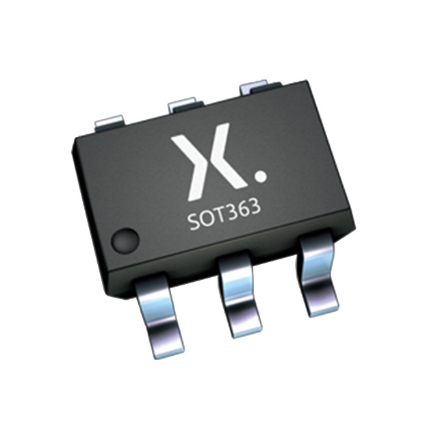
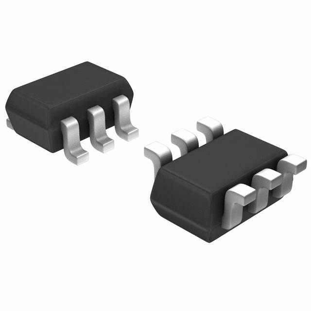
The PUMB9,115 is a pre-biased dual PNP bipolar junction transistor (BJT) manufactured by Nexperia USA Inc. in a 6-TSSOP surface mount package. This component integrates two PNP transistors with internal biasing resistors, designed for applications requiring compact switching and amplification functionality at 50V maximum collector-emitter breakdown voltage. The part maintains Active product status and carries AEC-Q100 automotive qualification with ROHS3 compliance.
Equivalent and substitute parts are identified when alternative manufacturers offer functionally compatible pre-biased dual PNP transistors that operate within the same electrical and mechanical parameter ranges, enabling design flexibility and supply chain continuity.
Substiute Parts
Key Parameters
| Parameter | Value | Unit |
|---|---|---|
| Transistor Type | 2 PNP - Pre-Biased (Dual) | — |
| Current - Collector (Ic) (Max) | 100 | mA |
| Voltage - Collector Emitter Breakdown (Max) | 50 | V |
| Resistor - Base (R1) | 10 | kOhms |
| Resistor - Emitter Base (R2) | 47 | kOhms |
| Power - Max | 300 | mW |
| Mounting Type | Surface Mount | — |
| Package / Case | 6-TSSOP, SC-88, SOT-363 | — |
| RoHS Status | ROHS3 Compliant | — |
| Grade | Automotive | — |
| Qualification | AEC-Q100 | — |
Substitute Part Grouping Explanation
Substitution eligibility for the PUMB9,115 is determined by strict alignment of the following critical parameters:
Mandatory Matching Parameters:
- Transistor Type: 2 PNP - Pre-Biased (Dual)
- Current - Collector (Ic) (Max): 100 mA
- Voltage - Collector Emitter Breakdown (Max): 50 V
- Mounting Type: Surface Mount
- Package / Case: 6-TSSOP, SC-88, SOT-363 (compatible pinout)
- RoHS Status: ROHS3 Compliant
Internal Biasing Resistor Configuration: The PUMB9,115 specifies R1 = 10 kOhms and R2 = 47 kOhms. Substitute parts must maintain identical or functionally equivalent internal resistor values to preserve circuit behavior and switching characteristics.
Acceptable Variations:
- Power dissipation (Max): Substitute parts may operate at lower maximum power ratings provided they meet application requirements
- DC Current Gain (hFE): Variations in minimum hFE are acceptable within the pre-biased transistor design envelope
- Vce Saturation: Minor variations are acceptable provided saturation voltage remains within typical circuit operating margins
- Frequency - Transition: Substitute parts may include transition frequency specifications not present in the main part
All substitute parts listed maintain Active product status and ROHS3 compliance, ensuring regulatory and supply continuity.
Parameter Comparison
| Parameter | PUMB9,115 (Nexperia) |
MUN5114DW1T1G (onsemi) |
DDA114YU-7-F (Diodes Inc.) |
UMB10NTN (Rohm) |
UMB11NTN (Rohm) |
UMB2NTN (Rohm) |
|---|---|---|---|---|---|---|
| Transistor Type | 2 PNP - Pre-Biased (Dual) | 2 PNP - Pre-Biased (Dual) | 2 PNP - Pre-Biased (Dual) | 2 PNP - Pre-Biased (Dual) | 2 PNP - Pre-Biased (Dual) | 2 PNP - Pre-Biased (Dual) |
| Current - Collector (Ic) (Max) | 100 mA | 100 mA | 100 mA | 100 mA | 100 mA | 100 mA |
| Voltage - Collector Emitter Breakdown (Max) | 50 V | 50 V | 50 V | 50 V | 50 V | 50 V |
| Resistor - Base (R1) | 10 kOhms | 10 kOhms | 10 kOhms | 2.2 kOhms | 10 kOhms | 47 kOhms |
| Resistor - Emitter Base (R2) | 47 kOhms | 47 kOhms | 47 kOhms | 47 kOhms | 10 kOhms | 47 kOhms |
| DC Current Gain (hFE) (Min) @ Ic, Vce | 100 @ 5mA, 5V | 80 @ 5mA, 10V | 68 @ 10mA, 5V | 80 @ 10mA, 5V | 20 @ 5mA, 5V | 68 @ 5mA, 5V |
| Vce Saturation (Max) @ Ib, Ic | 100mV @ 250µA, 5mA | 250mV @ 300µA, 10mA | 300mV @ 250µA, 5mA | 300mV @ 250µA, 5mA | 300mV @ 500µA, 10mA | 300mV @ 500µA, 10mA |
| Current - Collector Cutoff (Max) | 1 µA | 500 nA | 500 nA | 500 nA | 500 nA | 500 nA |
| Power - Max | 300 mW | 250 mW | 200 mW | 150 mW | 150 mW | 150 mW |
| Frequency - Transition | — | — | 250 MHz | 250 MHz | 250 MHz | 250 MHz |
| Mounting Type | Surface Mount | Surface Mount | Surface Mount | Surface Mount | Surface Mount | Surface Mount |
| Package / Case | 6-TSSOP, SC-88, SOT-363 | 6-TSSOP, SC-88, SOT-363 | 6-TSSOP, SC-88, SOT-363 | 6-TSSOP, SC-88, SOT-363 | 6-TSSOP, SC-88, SOT-363 | 6-TSSOP, SC-88, SOT-363 |
| RoHS Status | ROHS3 Compliant | ROHS3 Compliant | ROHS3 Compliant | ROHS3 Compliant | ROHS3 Compliant | ROHS3 Compliant |
| Product Status | Active | Active | Active | Active | Active | Active |
Engineering Selection Recommendations
Direct Substitutes (Identical Internal Resistor Configuration):
MUN5114DW1T1G (onsemi) and DDA114YU-7-F (Diodes Incorporated) maintain the R1 = 10 kOhms and R2 = 47 kOhms configuration matching the PUMB9,115. Both parts are Active status with ROHS3 compliance. MUN5114DW1T1G operates at 250 mW maximum power, while DDA114YU-7-F operates at 200 mW. Selection between these and the PUMB9,115 depends on application power budget requirements and supply availability.
Functionally Compatible Substitutes (Matching Core Electrical Parameters):
UMB10NTN (Rohm Semiconductor) maintains R1 = 10 kOhms but specifies R2 = 47 kOhms with 150 mW maximum power. This part is suitable for applications where lower power dissipation is acceptable.
UMB11NTN (Rohm Semiconductor) specifies R1 = 10 kOhms and R2 = 10 kOhms with 150 mW maximum power. The different emitter-base resistor value alters circuit biasing characteristics and is suitable only for applications designed to accommodate this configuration.
UMB2NTN (Rohm Semiconductor) specifies R1 = 47 kOhms and R2 = 47 kOhms with 150 mW maximum power. The higher base resistor value significantly alters biasing behavior and is suitable only for applications specifically designed for this resistor configuration.
Selection Criteria:
- For direct pin-compatible replacement with identical biasing behavior: Select MUN5114DW1T1G or DDA114YU-7-F
- For applications with reduced power budget: Select UMB10NTN
- For applications requiring alternative biasing networks: Select UMB11NTN or UMB2NTN only if circuit design accommodates the specified resistor values
- All substitute parts maintain Active product status and ROHS3 compliance, ensuring regulatory continuity
Frequently Asked Questions (FAQ)
Q: Can MUN5114DW1T1G replace PUMB9,115 in all applications?
A: MUN5114DW1T1G maintains identical internal resistor configuration (R1 = 10 kOhms, R2 = 47 kOhms) and maximum collector current (100 mA) and breakdown voltage (50 V). The primary difference is maximum power dissipation: MUN5114DW1T1G operates at 250 mW versus PUMB9,115 at 300 mW. Substitution is valid provided application power requirements do not exceed 250 mW.
Q: What is the significance of internal resistor values in pre-biased transistor selection?
A: Internal resistor values (R1 and R2) determine the biasing network behavior and switching characteristics of pre-biased transistors. R1 (base resistor) and R2 (emitter-base resistor) establish the transistor's turn-on threshold and current gain characteristics. Parts with different resistor values (such as UMB11NTN with R1 = 10 kOhms, R2 = 10 kOhms) produce different circuit behavior and are not interchangeable without circuit redesign.
Q: Are all listed substitute parts compatible with the PUMB9,115 package footprint?
A: All listed substitute parts are specified for 6-TSSOP, SC-88, and SOT-363 packages. These designations refer to the same physical package with identical pinout and footprint. Mechanical compatibility is confirmed across all substitute parts.
Q: What does AEC-Q100 qualification mean for automotive applications?
A: AEC-Q100 is an automotive industry qualification standard. The PUMB9,115 carries this qualification. Not all substitute parts explicitly list AEC-Q100 qualification in the provided data. For automotive applications requiring AEC-Q100 compliance, verify qualification status with the component manufacturer before selection.
Q: Can UMB2NTN substitute for PUMB9,115?
A: UMB2NTN specifies R1 = 47 kOhms and R2 = 47 kOhms, differing significantly from PUMB9,115 (R1 = 10 kOhms, R2 = 47 kOhms). The higher base resistor value alters biasing behavior and switching characteristics. Substitution is valid only for applications specifically designed to operate with this resistor configuration.
Q: What is the difference between Cut Tape (CT) and Tape & Reel (TR) packaging?
A: Cut Tape (CT) and Digi-Reel® packaging are supplied in individual cut segments, suitable for manual assembly or small-volume production. Tape & Reel (TR) packaging supplies components on continuous tape, suitable for automated assembly equipment. Both packaging formats contain identical components; selection depends on assembly process requirements.
Q: How do DC Current Gain (hFE) variations affect substitution decisions?
A: DC Current Gain (hFE) variations among substitute parts reflect different transistor characteristics. PUMB9,115 specifies hFE minimum of 100 @ 5mA, 5V, while substitute parts range from 20 to 100 depending on measurement conditions. For applications sensitive to current gain, verify that the substitute part's hFE specification meets circuit design requirements.
Q: Are all substitute parts ROHS3 compliant?
A: All listed substitute parts are specified as ROHS3 Compliant, ensuring regulatory compliance with hazardous substance restrictions. This compliance status is consistent across all alternatives.
Alternative Parts

SJ6012L2TP
Littelfuse Inc.
6 Alternative Parts

JMK107BBJ476MA-RE
Taiyo Yuden
10 Alternative Parts

GMK107BBJ475MA-T
Taiyo Yuden
5 Alternative Parts
SJ6020N2ARP
Littelfuse Inc.
3 Alternative Parts
SJ6025R2ATP
Littelfuse Inc.
4 Alternative Parts

2474-05L
API Delevan Inc.
1 Alternative Parts

4590R-684K
API Delevan Inc.
1 Alternative Parts

CM6560R-334
API Delevan Inc.
1 Alternative Parts

CM6460-104
API Delevan Inc.
1 Alternative Parts

5526-12
API Delevan Inc.
1 Alternative Parts