


Request Quote
(Ships tomorrow)
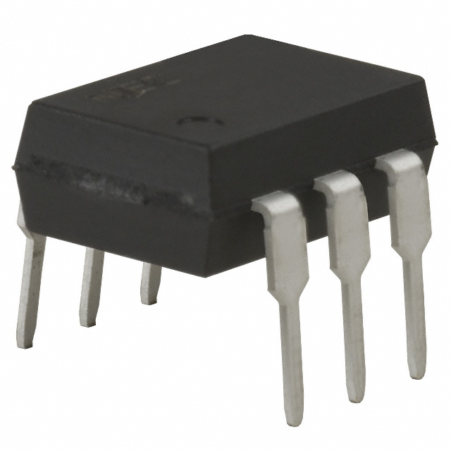
PS7342-1A-A Solid State Relay SPST-NO Equivalent & Substitute Parts
Part Overview
The PS7342-1A-A is a solid state relay (SSR) manufactured by CEL, configured as a single-pole single-throw normally open (SPST-NO) device in a 6-DIP through-hole package. This component is rated for 200 mA load current at 0–400 V AC/DC operation with a maximum on-state resistance of 10 Ohms. The part is classified as obsolete, making equivalent substitutes necessary for new designs and ongoing production requirements. Substitute parts must maintain functional compatibility across load voltage, current rating, input voltage, and package configuration.
Substiute Parts
Key Parameters
| Parameter | PS7342-1A-A |
|---|---|
| Manufacturer | CEL |
| Series | PS, OCMOS |
| Circuit Configuration | SPST-NO (1 Form A) |
| Output Type | AC, DC |
| Voltage - Input | 1.2 VDC |
| Voltage - Load | 0 V ~ 400 V |
| Load Current | 200 mA |
| On-State Resistance (Max) | 10 Ohms |
| Package / Case | 6-DIP (0.300", 7.62mm) |
| Mounting Type | Through Hole |
| Termination Style | PC Pin |
| Product Status | Obsolete |
Substitute Part Grouping Explanation
Substitution eligibility for the PS7342-1A-A is determined by the following critical parameters:
Mandatory Compatibility Criteria:
- Circuit configuration: SPST-NO (1 Form A)
- Package type: 6-DIP (0.300", 7.62mm)
- Mounting type: Through Hole
- Termination style: PC Pin
- Output type: AC, DC capable
- Input voltage: Must be compatible with or lower than 1.2 VDC
- Load voltage range: Must support 0–400 V operation
- Load current: Must support minimum 200 mA
Substitution Logic: The PS7342-1A-A operates at 200 mA with a maximum load voltage of 400 V. Substitute parts are grouped into two categories based on load current capability:
Category 1 – Full Current Equivalents (200 mA): Parts that maintain the 200 mA load current rating are direct functional equivalents. These parts support the full operational envelope of the original component.
Category 2 – Reduced Current Substitutes (150 mA): Parts rated for 150 mA load current represent a derating scenario. These substitutes are acceptable only when the application circuit operates at or below 150 mA. The 400 V load voltage capability is maintained.
All substitute candidates are manufactured by Panasonic Electric Works in the PhotoMOS™ AQV series, share identical package geometry, and maintain through-hole PC pin termination.
Parameter Comparison
| Parameter | PS7342-1A-A | AQV253H | AQV254 | AQV254H |
|---|---|---|---|---|
| Manufacturer | CEL | Panasonic Electric Works | Panasonic Electric Works | Panasonic Electric Works |
| Series | PS, OCMOS | PhotoMOS™ AQV | PhotoMOS™ AQV | PhotoMOS™ AQV |
| Circuit Configuration | SPST-NO (1 Form A) | SPST-NO (1 Form A) | SPST-NO (1 Form A) | SPST-NO (1 Form A) |
| Output Type | AC, DC | AC, DC | AC, DC | AC, DC |
| Voltage - Input | 1.2 VDC | 1.14 VDC | 1.14 VDC | 1.14 VDC |
| Voltage - Load | 0 V ~ 400 V | 0 V ~ 250 V | 0 V ~ 400 V | 0 V ~ 400 V |
| Load Current | 200 mA | 200 mA | 150 mA | 150 mA |
| On-State Resistance (Max) | 10 Ohms | 8 Ohms | 16 Ohms | 16 Ohms |
| Package / Case | 6-DIP (0.300", 7.62mm) | 6-DIP (0.300", 7.62mm) | 6-DIP (0.300", 7.62mm) | 6-DIP (0.300", 7.62mm) |
| Mounting Type | Through Hole | Through Hole | Through Hole | Through Hole |
| Termination Style | PC Pin | PC Pin | PC Pin | PC Pin |
| Product Status | Obsolete | Active | Active | Active |
| RoHS Status | Not specified | RoHS Compliant | ROHS3 Compliant | ROHS3 Compliant |
Engineering Selection Recommendations
AQV253H – Primary Substitute for Full Current Applications
The AQV253H is the preferred substitute when the application requires 200 mA load current capability. This part maintains electrical equivalence to the PS7342-1A-A with the following considerations:
- Load voltage is limited to 250 V maximum, compared to the original 400 V specification. This part is suitable only for applications operating at 0–250 V.
- Input voltage (1.14 VDC) is compatible with the original 1.2 VDC specification.
- On-state resistance (8 Ohms maximum) is superior to the original (10 Ohms maximum), resulting in lower power dissipation.
- Product status is Active with RoHS Compliant certification, ensuring long-term availability and environmental compliance.
- Packaging and mounting characteristics are identical to the original part.
AQV254 and AQV254H – Substitutes for 400 V Load Voltage Applications with Current Derating
Both AQV254 and AQV254H are suitable substitutes when the application requires 400 V load voltage capability but can operate at reduced load current (150 mA maximum). These parts are functionally equivalent with the following distinctions:
- Load voltage range (0–400 V) matches the original PS7342-1A-A specification.
- Load current is derated to 150 mA. These parts are not suitable for applications requiring the full 200 mA rating.
- Input voltage (1.14 VDC) is compatible with the original specification.
- On-state resistance (16 Ohms maximum) is higher than the original, resulting in increased power dissipation at rated current.
- Both parts are Active with ROHS3 Compliant certification.
- AQV254H is available in lower inventory (1,335 pcs) compared to AQV254 (16,747 pcs).
Selection Logic:
- If the application operates at 0–250 V and requires 200 mA: Select AQV253H.
- If the application operates at 0–400 V and can accept 150 mA maximum: Select AQV254 or AQV254H.
- If the application requires both 400 V and 200 mA: No direct substitute exists within the provided part list. Alternative sourcing or circuit redesign is required.
Frequently Asked Questions (FAQ)
Q1: Can the AQV253H replace the PS7342-1A-A in all applications?
A: The AQV253H is a functional substitute only for applications operating at load voltages of 250 V or lower. If your circuit requires the full 400 V load voltage capability of the original part, the AQV253H is not suitable. Verify the maximum load voltage in your application before selection.
Q2: What is the difference between AQV254 and AQV254H?
A: Both parts are electrically identical with the same electrical specifications (150 mA load current, 0–400 V load voltage, 16 Ohms maximum on-state resistance). The primary difference is inventory availability. AQV254 has 16,747 units in stock, while AQV254H has 1,335 units. Select based on procurement lead time and quantity requirements.
Q3: Why does the AQV254 have a lower load current rating (150 mA) than the PS7342-1A-A (200 mA)?
A: The AQV254 and AQV254H are designed with different internal characteristics that result in a 150 mA maximum load current rating while maintaining 400 V load voltage capability. This represents a design trade-off between current capacity and voltage rating. If your application requires both 200 mA and 400 V, these parts are not suitable.
Q4: Are all substitute parts compatible with the same PCB layout as the PS7342-1A-A?
A: Yes. All substitute parts (AQV253H, AQV254, AQV254H) use the identical 6-DIP (0.300", 7.62mm) package with PC pin termination and through-hole mounting. No PCB layout modifications are required for mechanical compatibility.
Q5: What is the input voltage compatibility between the PS7342-1A-A and the substitute parts?
A: The original PS7342-1A-A requires 1.2 VDC input. All substitute parts (AQV253H, AQV254, AQV254H) operate at 1.14 VDC input. This lower input voltage is compatible with standard logic-level control circuits and represents an improvement in input sensitivity.
Q6: Are the substitute parts RoHS compliant?
A: Yes. AQV253H is RoHS Compliant. AQV254 and AQV254H are ROHS3 Compliant. All substitute parts meet current environmental compliance requirements. The original PS7342-1A-A RoHS status is not specified.
Q7: What is the impact of higher on-state resistance in the AQV254 and AQV254H?
A: The AQV254 and AQV254H have a maximum on-state resistance of 16 Ohms, compared to 10 Ohms for the PS7342-1A-A. At 150 mA load current, this results in approximately 0.36 W additional power dissipation (I²R loss). Verify that your circuit thermal design accommodates this increased dissipation.
Q8: Can I use AQV254 in a 200 mA application if I derate the load current?
A: The AQV254 and AQV254H are rated for a maximum of 150 mA. Operating these parts above their rated current specification is not recommended and may result in premature failure or unpredictable behavior. If your application requires 200 mA, use the AQV253H (for 0–250 V) or source an alternative part rated for 200 mA at 400 V.
Alternative Parts

SJ6012L2TP
Littelfuse Inc.
6 Alternative Parts

JMK107BBJ476MA-RE
Taiyo Yuden
10 Alternative Parts

GMK107BBJ475MA-T
Taiyo Yuden
5 Alternative Parts
SJ6020N2ARP
Littelfuse Inc.
3 Alternative Parts
SJ6025R2ATP
Littelfuse Inc.
4 Alternative Parts

2474-05L
API Delevan Inc.
1 Alternative Parts

4590R-684K
API Delevan Inc.
1 Alternative Parts

CM6560R-334
API Delevan Inc.
1 Alternative Parts

CM6460-104
API Delevan Inc.
1 Alternative Parts

5526-12
API Delevan Inc.
1 Alternative Parts