


Request Quote
(Ships tomorrow)
PS7241-2B-A Solid State Relay: Equivalent & Substitute Parts
Part Overview
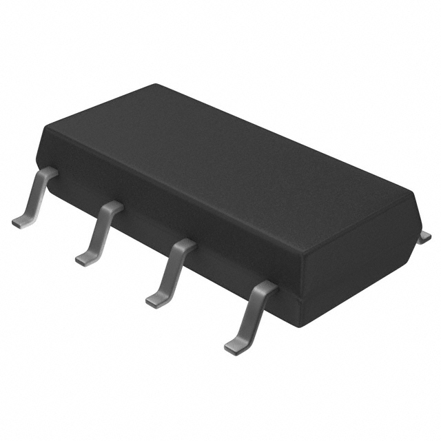
The PS7241-2B-A is a solid state relay (SSR) manufactured by CEL, configured as a SPST-NC (1 Form B) dual-channel device in an 8-SOP surface mount package. This component operates with a 1.2VDC input signal and controls AC/DC loads up to 400V at 120mA maximum load current. The PS7241-2B-A is classified as obsolete, making identification of functionally equivalent substitute parts essential for ongoing design support and production continuity.
Substiute Parts
Key Parameters
| Parameter | Value |
|---|---|
| Manufacturer Part Number | PS7241-2B-A |
| Manufacturer | CEL |
| Product Status | Obsolete |
| Circuit Configuration | SPST-NC (1 Form B) x 2 |
| Package / Case | 8-SOP (0.173", 4.40mm Width) |
| Mounting Type | Surface Mount |
| Voltage - Input | 1.2VDC |
| Voltage - Load | 0 V ~ 400 V |
| Load Current (Maximum) | 120 mA |
| Output Type | AC, DC |
| On-State Resistance (Max) | 30 Ohms |
| Termination Style | Gull Wing |
| Moisture Sensitivity Level (MSL) | 1 (Unlimited) |
Substitute Part Grouping Explanation
Substitution eligibility for the PS7241-2B-A is determined by strict alignment of the following electrical and mechanical parameters:
Critical Matching Parameters:
- Circuit configuration: SPST-NC (1 Form B) x 2 (dual-channel, normally closed)
- Package type: 8-SOP (0.173", 4.40mm Width)
- Mounting type: Surface Mount with Gull Wing termination
- Load voltage range: 0 V ~ 400 V
- Output type: AC and DC load support
- Input signal voltage: Compatible with 1.2VDC control signal
Allowable Variation Parameters:
- Load current: Substitute must support minimum 120mA (equal or greater capacity acceptable)
- On-state resistance: Substitute specifications must be documented and suitable for application requirements
- Input voltage: Substitute input voltage must be compatible with 1.2VDC control signal
The substitute parts AQW414S and AQW414SX meet these criteria. Both are manufactured by Panasonic Electric Works in the PhotoMOS™ AQW series, feature identical circuit configuration and package specifications, and support the same load voltage range and output types. Both substitutes are classified as active products with current manufacturing status.
Parameter Comparison
| Parameter | PS7241-2B-A (Main) | AQW414S | AQW414SX |
|---|---|---|---|
| Manufacturer | CEL | Panasonic Electric Works | Panasonic Electric Works |
| Product Status | Obsolete | Active | Active |
| Circuit Configuration | SPST-NC (1 Form B) x 2 | SPST-NC (1 Form B) x 2 | SPST-NC (1 Form B) x 2 |
| Package / Case | 8-SOP (0.173", 4.40mm Width) | 8-SOP (0.173", 4.40mm Width) | 8-SOP (0.173", 4.40mm Width) |
| Mounting Type | Surface Mount | Surface Mount | Surface Mount |
| Termination Style | Gull Wing | Gull Wing | Gull Wing |
| Voltage - Input | 1.2VDC | 1.14VDC | 1.14VDC |
| Voltage - Load | 0 V ~ 400 V | 0 V ~ 400 V | 0 V ~ 400 V |
| Load Current (Maximum) | 120 mA | 80 mA | 80 mA |
| Output Type | AC, DC | AC, DC | AC, DC |
| On-State Resistance (Max) | 30 Ohms | 50 Ohms | 50 Ohms |
| Packaging Format | Bulk | Tube | Tape & Reel (TR) |
| RoHS Status | Not specified | RoHS Compliant | RoHS Compliant |
| ECCN | EAR99 | EAR99 | EAR99 |
Engineering Selection Recommendations
Substitution Feasibility:
The AQW414S and AQW414SX are direct functional equivalents for the obsolete PS7241-2B-A. Both substitute parts maintain identical circuit topology, package geometry, and load voltage specifications. The primary design consideration is load current capacity: the substitutes are rated for 80mA maximum load current compared to the original 120mA specification. Applications requiring load currents exceeding 80mA are not suitable for these substitutes.
Compliance and Status:
Both AQW414S and AQW414SX are active products with current manufacturing support from Panasonic Electric Works. Both substitutes carry RoHS Compliant certification, providing environmental compliance advantages over the original PS7241-2B-A. Both parts share identical ECCN classification (EAR99) with the original component.
Packaging Considerations:
AQW414S is supplied in Tube packaging format. AQW414SX is supplied in Tape & Reel (TR) format. Selection between these two substitutes depends on production volume requirements and assembly process specifications. Both maintain identical electrical and mechanical specifications.
Input Voltage Compatibility:
The substitute parts operate at 1.14VDC input voltage compared to the original 1.2VDC specification. This represents a 5% reduction in input voltage requirement and is compatible with standard 1.2VDC control signal sources.
Frequently Asked Questions (FAQ)
Q: Can AQW414S or AQW414SX be used as direct replacements for PS7241-2B-A in existing designs?
A: Yes, both AQW414S and AQW414SX are functionally equivalent substitutes. They share identical circuit configuration (SPST-NC x 2), package type (8-SOP), mounting method (surface mount), and load voltage range (0-400V AC/DC). PCB layout and footprint compatibility are maintained. The primary design constraint is load current: applications limited to 80mA or less are fully compatible. Applications requiring the original 120mA load current capacity require design modification or alternative component selection.
Q: What is the difference between AQW414S and AQW414SX?
A: AQW414S and AQW414SX are electrically and mechanically identical. The difference is packaging format only. AQW414S is supplied in Tube packaging; AQW414SX is supplied in Tape & Reel (TR) format. Selection depends on production volume and assembly equipment compatibility. Both parts carry identical part specifications and RoHS compliance status.
Q: Are there any input voltage compatibility issues when substituting?
A: The substitute parts operate at 1.14VDC input voltage versus the original 1.2VDC. This 5% reduction is within standard control signal tolerances and presents no compatibility issues with 1.2VDC control sources. Both input voltages are compatible with standard logic-level control circuits.
Q: What is the impact of the 80mA load current limit on substitution?
A: The substitute parts are rated for 80mA maximum load current compared to the original 120mA specification. Applications with load currents at or below 80mA are fully compatible. Applications requiring load currents between 80mA and 120mA cannot use these substitutes without design modification. Load current requirements must be verified against application specifications before substitution.
Q: Do the substitute parts have better compliance status?
A: Yes. Both AQW414S and AQW414SX carry RoHS Compliant certification. The original PS7241-2B-A RoHS status is not specified. Both substitutes maintain identical ECCN classification (EAR99) for export control purposes.
Q: Is on-state resistance a concern when substituting?
A: The substitute parts have 50 Ohm maximum on-state resistance compared to the original 30 Ohm specification. This represents a 67% increase in resistance. For applications where on-state voltage drop is critical, this difference must be evaluated against load current and application requirements. At 80mA load current, the substitute produces 4V maximum on-state voltage drop versus 2.4V for the original part.
Alternative Parts

SJ6012L2TP
Littelfuse Inc.
6 Alternative Parts

JMK107BBJ476MA-RE
Taiyo Yuden
10 Alternative Parts

GMK107BBJ475MA-T
Taiyo Yuden
5 Alternative Parts
SJ6020N2ARP
Littelfuse Inc.
3 Alternative Parts
SJ6025R2ATP
Littelfuse Inc.
4 Alternative Parts

2474-05L
API Delevan Inc.
1 Alternative Parts

4590R-684K
API Delevan Inc.
1 Alternative Parts

CM6560R-334
API Delevan Inc.
1 Alternative Parts

CM6460-104
API Delevan Inc.
1 Alternative Parts

5526-12
API Delevan Inc.
1 Alternative Parts