


Request Quote
(Ships tomorrow)
PS7141-2B-A Equivalent & Substitute Parts
Part Overview
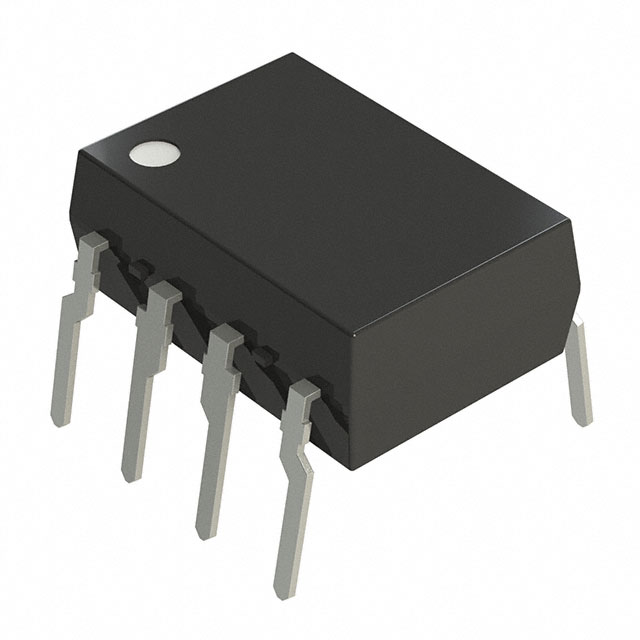
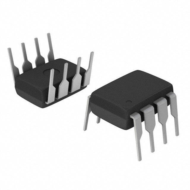
The PS7141-2B-A is a Solid State SPST-NC (1 Form B) relay manufactured by CEL in 8-DIP packaging. This component operates as a dual-channel relay with a maximum load current of 150 mA and rated for 0–400 V AC/DC applications. The product status is Obsolete, necessitating identification of active substitute components that maintain functional compatibility for existing designs or new production requirements.
Substiute Parts
Key Parameters
| Parameter | Value |
|---|---|
| Manufacturer Part Number | PS7141-2B-A |
| Manufacturer | CEL |
| Circuit Configuration | SPST-NC (1 Form B) x 2 |
| Package / Case | 8-DIP (0.300", 7.62mm) |
| Mounting Type | Through Hole |
| Termination Style | PC Pin |
| Voltage - Input | 1.2 VDC |
| Voltage - Load | 0 V ~ 400 V |
| Load Current | 150 mA |
| Output Type | AC, DC |
| On-State Resistance (Max) | 30 Ohms |
| Product Status | Obsolete |
Substitute Part Grouping Explanation
Substitution eligibility is determined by the following critical parameters:
- Package / Case: 8-DIP (0.300", 7.62mm) — identical across all substitutes
- Mounting Type: Through Hole — consistent across all candidates
- Termination Style: PC Pin — maintained for PCB compatibility
- Voltage - Load Range: 0 V ~ 400 V — all substitutes support this range
- Output Type: AC, DC — supported by all alternatives
- Circuit Configuration: SPST-NC (1 Form B) x 2 — primary functional requirement
Substitutes are grouped based on whether they maintain the SPST-NC circuit configuration (normally closed) and whether load current and on-state resistance specifications align with application requirements. The PS7141-2B-A specifies 150 mA maximum load current; substitutes with equal or greater current capability are electrically compatible. Input voltage requirements (1.2 VDC for PS7141-2B-A versus 1.14 VDC for Panasonic alternatives) are within typical design tolerances for SSR control circuits.
Parameter Comparison
| Parameter | PS7141-2B-A | AQW414EH | AQW454 | AQW414 | AQW254 |
|---|---|---|---|---|---|
| Manufacturer | CEL | Panasonic Electric Works | Panasonic Electric Works | Panasonic Electric Works | Panasonic Electric Works |
| Series | PS, OCMOS | PhotoMOS™ AQW | PhotoMOS™ AQW | PhotoMOS™ AQW | PhotoMOS™ AQW |
| Circuit Configuration | SPST-NC (1 Form B) x 2 | SPST-NC (1 Form B) x 2 | SPST-NC (1 Form B) x 2 | SPST-NC (1 Form B) x 2 | SPST-NO (1 Form A) x 2 |
| Package / Case | 8-DIP (0.300", 7.62mm) | 8-DIP (0.300", 7.62mm) | 8-DIP (0.300", 7.62mm) | 8-DIP (0.300", 7.62mm) | 8-DIP (0.300", 7.62mm) |
| Voltage - Input | 1.2 VDC | 1.14 VDC | 1.14 VDC | 1.14 VDC | 1.14 VDC |
| Voltage - Load | 0 V ~ 400 V | 0 V ~ 400 V | 0 V ~ 400 V | 0 V ~ 400 V | 0 V ~ 400 V |
| Load Current | 150 mA | 100 mA | 120 mA | 100 mA | 120 mA |
| On-State Resistance (Max) | 30 Ohms | 35 Ohms | 16 Ohms | 50 Ohms | 16 Ohms |
| Product Status | Obsolete | Active | Active | Active | Active |
| RoHS Status | Not specified | ROHS3 Compliant | RoHS Compliant | ROHS3 Compliant | ROHS3 Compliant |
| REACH Status | REACH Affected | REACH Unaffected | Not specified | REACH Unaffected | REACH Unaffected |
Engineering Selection Recommendations
Primary Substitutes (SPST-NC Configuration Maintained):
AQW414EH, AQW454, and AQW414 maintain the SPST-NC (1 Form B) circuit configuration identical to the PS7141-2B-A. All three are Active products with ROHS3 Compliance status and REACH Unaffected designation, supporting current regulatory requirements. The AQW454 and AQW414EH both support 120 mA load current, which exceeds the PS7141-2B-A's 150 mA specification for applications requiring less than 120 mA. The AQW414 supports 100 mA, suitable for designs requiring up to 100 mA. On-state resistance varies: AQW414EH provides 35 Ohms, AQW454 and AQW254 provide 16 Ohms, and AQW414 provides 50 Ohms. Selection between these three depends on load current requirements and acceptable on-state resistance for the specific application.
Secondary Consideration (SPST-NO Configuration):
The AQW254 differs functionally from the PS7141-2B-A by providing SPST-NO (1 Form A) circuit configuration rather than SPST-NC. This part is not suitable as a direct replacement in applications requiring normally closed contact behavior but may apply to designs using only normally open functionality. The AQW254 is an Active product with ROHS3 Compliance and REACH Unaffected status.
Frequently Asked Questions (FAQ)
Q: Can the AQW254 replace the PS7141-2B-A? A: The AQW254 is electrically compatible in package, voltage, and footprint but differs in circuit configuration. The PS7141-2B-A is SPST-NC (normally closed), while the AQW254 is SPST-NO (normally open). Direct substitution is not possible if the application depends on normally closed contact behavior.
Q: What are the load current requirements for selecting a substitute? A: The PS7141-2B-A specifies 150 mA maximum load current. The AQW454 and AQW254 support 120 mA, while the AQW414 and AQW414EH support 100 mA. Select a substitute rated for the actual application load current or lower. If your design draws more than the substitute's rated current, an alternative approach is required.
Q: Are all substitutes compatible with the same PCB footprint? A: Yes. All substitute parts share the 8-DIP (0.300", 7.62mm) package and PC Pin termination, ensuring through-hole PCB compatibility without layout modifications.
Q: What compliance differences should I consider? A: The PS7141-2B-A is REACH Affected, while all Panasonic substitutes (AQW414EH, AQW454, AQW414, AQW254) are REACH Unaffected and ROHS3 Compliant. For applications in regulated markets, the active substitutes offer improved compliance status.
Q: How do input voltage differences affect substitution? A: The PS7141-2B-A requires 1.2 VDC input, while Panasonic alternatives require 1.14 VDC. This 0.06 VDC difference is within typical SSR control circuit tolerances and does not preclude substitution.
Q: Which substitute offers the lowest on-state resistance? A: The AQW454 and AQW254 both provide 16 Ohms maximum on-state resistance, lower than the PS7141-2B-A at 30 Ohms. Applications sensitive to resistive voltage drop may benefit from these options.
Alternative Parts

SJ6012L2TP
Littelfuse Inc.
6 Alternative Parts

JMK107BBJ476MA-RE
Taiyo Yuden
10 Alternative Parts

GMK107BBJ475MA-T
Taiyo Yuden
5 Alternative Parts
SJ6020N2ARP
Littelfuse Inc.
3 Alternative Parts
SJ6025R2ATP
Littelfuse Inc.
4 Alternative Parts

2474-05L
API Delevan Inc.
1 Alternative Parts

4590R-684K
API Delevan Inc.
1 Alternative Parts

CM6560R-334
API Delevan Inc.
1 Alternative Parts

CM6460-104
API Delevan Inc.
1 Alternative Parts

5526-12
API Delevan Inc.
1 Alternative Parts