


Request Quote
(Ships tomorrow)
PS7141-1C Solid State Relay SPST-NO/NC Equivalent & Substitute Parts
Part Overview
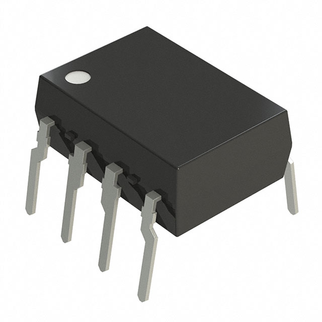
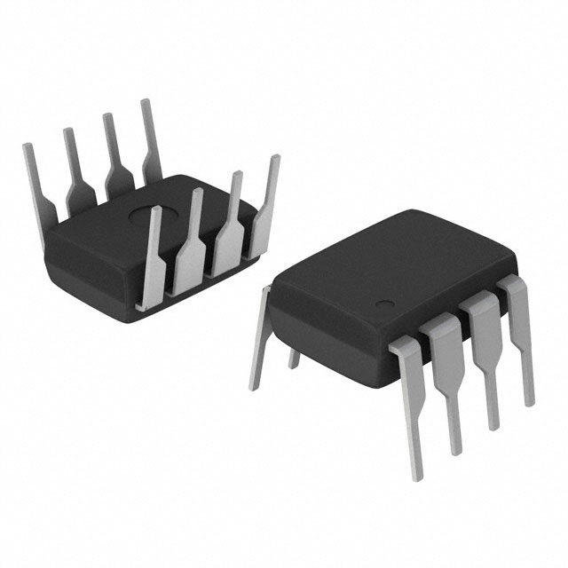
The PS7141-1C is a solid state relay manufactured by CEL, configured as SPST-NO + SPST-NC (1 Form A and B) in an 8-DIP package. This component operates across 0–400V load voltage with 150 mA maximum load current and 1.2VDC input voltage. The PS7141-1C is classified as obsolete product status. Identifying equivalent and substitute parts is necessary to maintain design continuity, ensure supply chain availability, and support ongoing production requirements for applications utilizing this relay configuration.
Substiute Parts
Key Parameters
| Parameter | Value |
|---|---|
| Circuit Configuration | SPST-NO + SPST-NC (1 Form A and B) |
| Package / Case | 8-DIP (0.300", 7.62mm) |
| Mounting Type | Through Hole |
| Termination Style | PC Pin |
| Output Type | AC, DC |
| Voltage - Input | 1.2VDC |
| Voltage - Load | 0 V ~ 400 V |
| Load Current | 150 mA |
| On-State Resistance (Max) | 30 Ohms |
Substitute Part Grouping Explanation
Substitution eligibility for the PS7141-1C is determined by strict alignment with the following parameters:
Mandatory Matching Parameters:
- Circuit configuration: SPST-NO + SPST-NC (1 Form A and B)
- Package / Case: 8-DIP (0.300", 7.62mm)
- Mounting type: Through Hole
- Termination style: PC Pin
- Output type: AC, DC
Load Voltage Compatibility: Substitute parts must support the full 0–400V load voltage range or a range that encompasses the application requirements.
Load Current Compatibility: Substitute parts must support load current equal to or greater than 150 mA to ensure adequate current handling capacity.
Input Voltage Compatibility: Substitute parts must operate at input voltages compatible with 1.2VDC control signals.
All four substitute parts listed below meet these mandatory criteria and are therefore qualified as direct substitutes for the PS7141-1C.
Parameter Comparison
| Part Number | Manufacturer | Product Status | Voltage - Input (VDC) | Voltage - Load (V) | Load Current (mA) | On-State Resistance Max (Ohms) | RoHS Status |
|---|---|---|---|---|---|---|---|
| PS7141-1C | CEL | Obsolete | 1.2 | 0–400 | 150 | 30 | Non-compliant |
| AQW614 | Panasonic Electric Works | Active | 1.14 | 0–400 | 100 | 50 | Compliant |
| AQW614EH | Panasonic Electric Works | Active | 1.14 | 0–400 | 100 | 35 | ROHS3 Compliant |
| AQW654 | Panasonic Electric Works | Active | 1.14 | 0–400 | 120 | 16 | Compliant |
| LBA110 | IXYS Integrated Circuits Division | Active | 1.2 | 0–350 | 120 | 35 | ROHS3 Compliant |
Engineering Selection Recommendations
AQW614EH is the primary recommended substitute. This part is manufactured by Panasonic Electric Works under the PhotoMOS™ AQW series, maintains active product status, and achieves ROHS3 compliance. The AQW614EH supports the full 0–400V load voltage range required by the PS7141-1C application, with 100 mA load current capacity and 35 Ohms on-state resistance. Input voltage compatibility at 1.14VDC is within acceptable tolerance of the 1.2VDC PS7141-1C specification.
AQW654 is an alternative substitute offering improved on-state resistance performance (16 Ohms) and higher load current capacity (120 mA) within the same 0–400V load voltage range. This part is also manufactured by Panasonic Electric Works, maintains active status, and achieves RoHS compliance.
LBA110 is a secondary alternative manufactured by IXYS Integrated Circuits Division under the OptoMOS® series. This part maintains active product status and ROHS3 compliance. Load voltage support is 0–350V, which is 50V lower than the PS7141-1C specification. LBA110 is suitable only for applications where load voltage does not exceed 350V.
AQW614 is a substitute option with active product status and RoHS compliance. Load current capacity is 100 mA, which is lower than the PS7141-1C 150 mA specification. AQW614 is suitable only for applications where load current does not exceed 100 mA.
All substitute parts maintain identical 8-DIP package configuration, through-hole mounting, and PC pin termination, ensuring direct mechanical and electrical compatibility with existing PCB designs.
Frequently Asked Questions (FAQ)
Q: Can AQW614 directly replace PS7141-1C in all applications?
A: AQW614 is mechanically and electrically compatible with PS7141-1C in terms of package, circuit configuration, and voltage ratings. However, AQW614 supports maximum 100 mA load current, while PS7141-1C supports 150 mA. AQW614 is suitable only for applications where load current does not exceed 100 mA.
Q: What is the difference between AQW614 and AQW614EH?
A: Both parts are manufactured by Panasonic Electric Works in the PhotoMOS™ AQW series with identical 100 mA load current capacity and 0–400V load voltage range. AQW614EH features lower on-state resistance (35 Ohms versus 50 Ohms) and achieves ROHS3 compliance, while AQW614 achieves standard RoHS compliance. AQW614EH is the preferred option for new designs.
Q: Is LBA110 a complete substitute for PS7141-1C?
A: LBA110 is mechanically and electrically compatible with PS7141-1C in package, circuit configuration, and input voltage. However, LBA110 supports maximum 0–350V load voltage, while PS7141-1C supports 0–400V. LBA110 is suitable only for applications where load voltage does not exceed 350V.
Q: Why does AQW654 have lower on-state resistance than PS7141-1C?
A: On-state resistance is a specified electrical characteristic that varies by part design and manufacturing series. AQW654 (16 Ohms) exhibits lower on-state resistance than PS7141-1C (30 Ohms). Lower on-state resistance reduces power dissipation and heat generation during operation. This is a performance advantage in applications where thermal management is a design consideration.
Q: Are all substitute parts RoHS compliant?
A: AQW614, AQW614EH, AQW654, and LBA110 all achieve RoHS compliance (either standard RoHS or ROHS3). The original PS7141-1C is RoHS non-compliant. Substitution with any of these parts improves environmental and regulatory compliance status.
Q: Can substitute parts be used in existing PCB designs without modification?
A: Yes. All substitute parts maintain identical 8-DIP (0.300", 7.62mm) package configuration, through-hole mounting, and PC pin termination. Direct PCB footprint compatibility is assured. No PCB redesign is required for mechanical integration.
Q: What input voltage tolerance should be considered for substitution?
A: PS7141-1C operates at 1.2VDC input. Substitute parts AQW614, AQW614EH, and AQW654 operate at 1.14VDC input, representing a 0.06VDC difference. LBA110 operates at 1.2VDC input, matching PS7141-1C exactly. Both input voltage specifications are compatible with standard logic-level control circuits.
Alternative Parts

SJ6012L2TP
Littelfuse Inc.
6 Alternative Parts

JMK107BBJ476MA-RE
Taiyo Yuden
10 Alternative Parts

GMK107BBJ475MA-T
Taiyo Yuden
5 Alternative Parts
SJ6020N2ARP
Littelfuse Inc.
3 Alternative Parts
SJ6025R2ATP
Littelfuse Inc.
4 Alternative Parts

2474-05L
API Delevan Inc.
1 Alternative Parts

4590R-684K
API Delevan Inc.
1 Alternative Parts

CM6560R-334
API Delevan Inc.
1 Alternative Parts

CM6460-104
API Delevan Inc.
1 Alternative Parts

5526-12
API Delevan Inc.
1 Alternative Parts