


Request Quote
(Ships tomorrow)
PS7113L-2A-A Solid State Relay - Equivalent & Substitute Parts
Part Overview
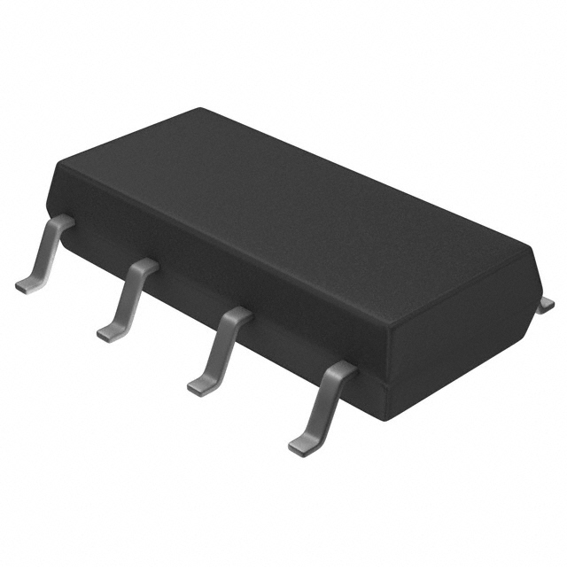
The PS7113L-2A-A is a solid-state relay (SSR) manufactured by CEL, configured as a SPST-NO (1 Form A) dual-channel device rated for 350 mA load current at 0-100 V output. This product is classified as obsolete, making identification of suitable substitutes necessary for new designs and ongoing maintenance. Equivalent parts must maintain compatible electrical specifications and identical surface-mount packaging to ensure drop-in replacement capability.
Substiute Parts
Key Parameters
| Parameter | Specification |
|---|---|
| Manufacturer Part Number | PS7113L-2A-A |
| Manufacturer | CEL |
| Circuit Configuration | SPST-NO (1 Form A) x 2 |
| Load Current Rating | 350 mA |
| Load Voltage Range | 0 V to 100 V |
| Input Voltage | 1.2 VDC |
| Output Type | AC, DC |
| On-State Resistance (Max) | 2.5 Ohms |
| Mounting Type | Surface Mount |
| Package / Case | 8-SMD (0.300", 7.62mm) |
| Termination Style | Gull Wing |
| Product Status | Obsolete |
| Moisture Sensitivity Level | 1 (Unlimited) |
Substitute Part Grouping Explanation
Substitution of the PS7113L-2A-A is determined by the following critical parameters:
Required Compatibility Criteria:
- Circuit configuration: SPST-NO (1 Form A) x 2
- Mounting type: Surface Mount
- Package type: 8-SMD (0.300", 7.62mm) with Gull Wing termination
- Input voltage: 1.2 VDC
- Output type: AC and DC support
- Load voltage range: must accommodate 0-100 V operation
- Load current: must support or exceed 350 mA
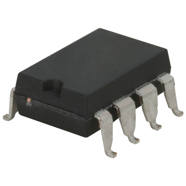
The PAA132S from IXYS Integrated Circuits Division satisfies all mandatory substitution criteria. While the PAA132S offers reduced maximum load voltage (0-60 V) and increased load current capability (600 mA) with improved on-state resistance (1 Ohm), it maintains identical circuit configuration, package geometry, and input voltage specifications. This device qualifies as a direct electrical and mechanical substitute where load voltage does not exceed 60 V.
Parameter Comparison
| Parameter | PS7113L-2A-A (CEL) | PAA132S (IXYS) |
|---|---|---|
| Manufacturer Part Number | PS7113L-2A-A | PAA132S |
| Manufacturer | CEL | IXYS Integrated Circuits Division |
| Circuit Configuration | SPST-NO (1 Form A) x 2 | SPST-NO (1 Form A) x 2 |
| Load Current Rating | 350 mA | 600 mA |
| Load Voltage Range | 0 V to 100 V | 0 V to 60 V |
| Input Voltage | 1.2 VDC | 1.2 VDC |
| Output Type | AC, DC | AC, DC |
| On-State Resistance (Max) | 2.5 Ohms | 1 Ohms |
| Mounting Type | Surface Mount | Surface Mount |
| Package / Case | 8-SMD (0.300", 7.62mm) | 8-SMD (0.300", 7.62mm) |
| Termination Style | Gull Wing | Gull Wing |
| Product Status | Obsolete | Active |
| RoHS Status | Not specified | ROHS3 Compliant |
| Moisture Sensitivity Level | 1 (Unlimited) | 1 (Unlimited) |
Engineering Selection Recommendations
The PAA132S qualifies as a suitable substitute for the PS7113L-2A-A based on the following:
-
Product Status: The original PS7113L-2A-A is classified as obsolete, establishing immediate necessity for substitution in active designs. The PAA132S maintains active product status with established supply chain availability.
-
Regulatory Compliance: The PAA132S is certified as ROHS3 compliant, meeting modern regulatory requirements for electronic components. The original device status lacks this certification detail.
-
Electrical Compatibility: Both devices operate with identical 1.2 VDC input voltage and support dual SPST-NO circuit topology with AC/DC output capability. The PAA132S delivers superior electrical performance through reduced on-state resistance (1 Ohm versus 2.5 Ohms) and higher load current capacity (600 mA versus 350 mA).
-
Physical Substitutability: Identical 8-SMD (0.300", 7.62mm) package geometry with gull wing termination enables direct board-level replacement without layout modification.
Substitution Constraint: The PAA132S maximum load voltage rating of 60 V restricts its use to applications where load voltage does not exceed this threshold. Applications requiring sustained operation above 60 V require alternative sourcing strategies.
Frequently Asked Questions (FAQ)
Q: Can the PAA132S directly replace the PS7113L-2A-A on existing PCBs?
A: Yes, the PAA132S provides identical pinout and package footprint (8-SMD, 0.300" pitch). No board redesign is required for mechanical substitution. Electrical compatibility is confirmed provided load voltage does not exceed 60 V.
Q: What is the significance of the load voltage difference between these devices?
A: The PS7113L-2A-A supports load voltages from 0-100 V, while the PAA132S operates over 0-60 V. This represents the primary electrical constraint governing substitution eligibility. Designs operating exclusively within the 0-60 V range utilize the PAA132S without derating.
Q: How does the on-state resistance difference affect circuit performance?
A: The PAA132S exhibits 1 Ohm maximum on-state resistance compared to 2.5 Ohms in the PS7113L-2A-A. This improvement reduces conduction losses and heat dissipation, benefiting thermal management in power-switching applications.
Q: Does the higher load current rating of the PAA132S affect substitution compatibility?
A: The PAA132S 600 mA rating exceeds the PS7113L-2A-A 350 mA specification. This represents improved headroom for current handling and does not introduce substitution constraints. Applications designed for 350 mA operate within the PAA132S rating with margin.
Q: What regulatory certifications should guide component selection?
A: The PAA132S ROHS3 compliance satisfies current regulatory requirements for commercial and industrial applications. Designs subject to specific regulatory frameworks should confirm certification alignment with applicable standards.
Alternative Parts

SJ6012L2TP
Littelfuse Inc.
6 Alternative Parts

JMK107BBJ476MA-RE
Taiyo Yuden
10 Alternative Parts

GMK107BBJ475MA-T
Taiyo Yuden
5 Alternative Parts
SJ6020N2ARP
Littelfuse Inc.
3 Alternative Parts
SJ6025R2ATP
Littelfuse Inc.
4 Alternative Parts

2474-05L
API Delevan Inc.
1 Alternative Parts

4590R-684K
API Delevan Inc.
1 Alternative Parts

CM6560R-334
API Delevan Inc.
1 Alternative Parts

CM6460-104
API Delevan Inc.
1 Alternative Parts

5526-12
API Delevan Inc.
1 Alternative Parts