


Request Quote
(Ships tomorrow)
PDTC144WE,115 Equivalent & Substitute Parts
Part Overview
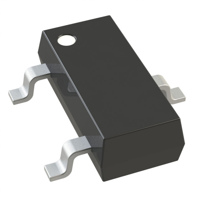
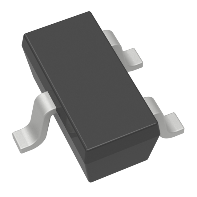
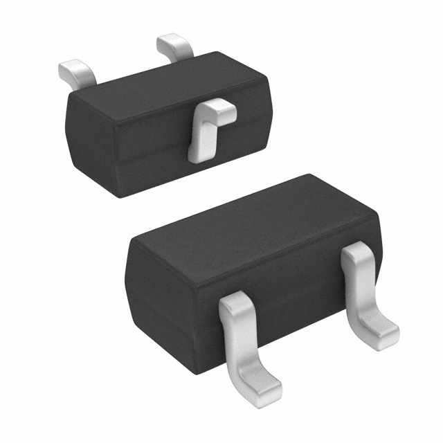
The PDTC144WE,115 is a pre-biased NPN bipolar junction transistor (BJT) manufactured by NXP USA Inc., designed for surface mount applications in the SC-75 (SOT-416) package. This component integrates internal base and emitter resistors, enabling simplified circuit design for switching and amplification applications with a maximum collector current of 100 mA and collector-emitter breakdown voltage of 50 V.
The PDTC144WE,115 is classified as obsolete. Equivalent and substitute parts are available from active product lines, offering improved availability and extended product lifecycle support while maintaining electrical and mechanical compatibility within specified parameter ranges.
Substiute Parts
Key Parameters
| Parameter | Value | Unit |
|---|---|---|
| Transistor Type | NPN - Pre-Biased | — |
| Current - Collector (Ic) Max | 100 | mA |
| Voltage - Collector Emitter Breakdown (Max) | 50 | V |
| Resistor - Base (R1) | 47 | kOhms |
| Resistor - Emitter Base (R2) | 22 | kOhms |
| DC Current Gain (hFE) Min @ Ic, Vce | 60 @ 5mA, 5V | — |
| Vce Saturation (Max) @ Ib, Ic | 150 | mV @ 500µA, 10mA |
| Current - Collector Cutoff (Max) | 1 | µA |
| Power - Max | 150 | mW |
| Mounting Type | Surface Mount | — |
| Package / Case | SC-75, SOT-416 | — |
| RoHS Status | ROHS3 Compliant | — |
| Moisture Sensitivity Level (MSL) | 1 (Unlimited) | — |
Substitute Part Grouping Explanation
Substitution of the PDTC144WE,115 is determined by the following critical parameters:
Electrical Compatibility Requirements:
- Transistor type: NPN - Pre-Biased
- Maximum collector current: 100 mA
- Collector-emitter breakdown voltage: 50 V
- Internal resistor configuration: R1 = 47 kOhms, R2 = 22 kOhms
- DC current gain (hFE) minimum: 60 @ 5mA, 5V
- Vce saturation: 150 mV @ 500µA, 10mA
- Maximum collector cutoff current: 1 µA
- Power dissipation: 150 mW
Mechanical Compatibility Requirements:
- Mounting type: Surface Mount
- Package options: SC-75 (SOT-416), SOT-323, SOT-23-3, SOT-523, DFN1006-3, DFN1006B-3, TO-236AB
Substitute parts must maintain all electrical parameters within the specified ranges. Package variations are acceptable provided the footprint and pin configuration are compatible with the application circuit design. Parts with identical internal resistor values (R1 = 47 kOhms, R2 = 22 kOhms) are direct electrical equivalents.
Parameter Comparison
| Part Number | Manufacturer | Ic Max (mA) | Vce Breakdown (V) | R1 (kOhms) | R2 (kOhms) | hFE Min @ 5mA, 5V | Vce Sat (mV) | Power Max (mW) | Package | Status |
|---|---|---|---|---|---|---|---|---|---|---|
| PDTC144WE,115 | NXP USA Inc. | 100 | 50 | 47 | 22 | 60 | 150 | 150 | SC-75 | Obsolete |
| DDTC144WE-7-F | Diodes Incorporated | 100 | 50 | 47 | 22 | 56 | 300 | 150 | SOT-523 | Active |
| DTC144EET1G | onsemi | 100 | 50 | 47 | 47 | 80 | 250 | 200 | SC-75 | Active |
| PDTC144WM,315 | NXP Semiconductors | 100 | 50 | 47 | 22 | 60 | 150 | 250 | DFN1006-3 | Active |
| PDTC144WMB,315 | NXP USA Inc. | 100 | 50 | 47 | 22 | 60 | 150 | 250 | DFN1006B-3 | Active |
| PDTC144WT,215 | Nexperia USA Inc. | 100 | 50 | 47 | 22 | 60 | 150 | 250 | TO-236AB | Active |
| PDTC144WU,115 | NXP USA Inc. | 100 | 50 | 47 | 22 | 60 | 150 | 200 | SOT-323 | Active |
| DDTC144TUA-7-F | Diodes Incorporated | 100 | 50 | 47 | — | 100 | 300 | 200 | SOT-323 | Active |
| DDTC144TCA-7-F | Diodes Incorporated | 100 | 50 | 47 | — | 100 | 300 | 200 | SOT-23-3 | Active |
| DDTC144TE-7-F | Diodes Incorporated | 100 | 50 | 47 | — | 100 | 300 | 150 | SOT-523 | Active |
| DDTC144GUA-7-F | Diodes Incorporated | 100 | 50 | — | 47 | 68 | 300 | 200 | SOT-323 | Active |
Engineering Selection Recommendations
Direct Electrical Equivalents (Identical R1 and R2 Values):
The following parts maintain identical internal resistor configurations (R1 = 47 kOhms, R2 = 22 kOhms) and are direct electrical substitutes for the PDTC144WE,115:
- PDTC144WM,315 (NXP Semiconductors): Active status, DFN1006-3 package, 250 mW power rating
- PDTC144WMB,315 (NXP USA Inc.): Active status, DFN1006B-3 package, 250 mW power rating, 230 MHz transition frequency
- PDTC144WT,215 (Nexperia USA Inc.): Active status, TO-236AB package, 250 mW power rating, AEC-Q100 automotive qualification
- PDTC144WU,115 (NXP USA Inc.): Active status, SOT-323 package, 200 mW power rating
- DDTC144WE-7-F (Diodes Incorporated): Active status, SOT-523 package, 150 mW power rating
Alternative Configurations (Modified R2 or R1 Values):
The following parts feature different internal resistor configurations and require circuit evaluation:
- DDTC144TUA-7-F (Diodes Incorporated): R1 = 47 kOhms only (R2-only series), SOT-323 package, 200 mW, active status
- DDTC144TCA-7-F (Diodes Incorporated): R1 = 47 kOhms only, SOT-23-3 package, 200 mW, active status
- DDTC144TE-7-F (Diodes Incorporated): R1 = 47 kOhms only, SOT-523 package, 150 mW, active status
- DDTC144GUA-7-F (Diodes Incorporated): R2 = 47 kOhms only (R2-only series), SOT-323 package, 200 mW, active status
Package Compatibility Considerations:
All substitute parts are surface mount devices. Package selection depends on PCB layout constraints and assembly equipment capabilities. The SC-75 (SOT-416) package of the original part is matched by DTC144EET1G (onsemi). Alternative packages (SOT-323, SOT-23-3, SOT-523, DFN1006-3, TO-236AB) require PCB footprint redesign.
Compliance and Certification:
All listed substitute parts maintain ROHS3 compliance and MSL 1 (Unlimited) moisture sensitivity rating. PDTC144WT,215 carries AEC-Q100 automotive qualification for applications requiring automotive-grade components.
Frequently Asked Questions (FAQ)
Q: Can PDTC144WU,115 replace PDTC144WE,115 directly?
A: Yes. Both parts share identical electrical parameters (R1 = 47 kOhms, R2 = 22 kOhms, Ic = 100 mA, Vce = 50 V, hFE = 60 @ 5mA, 5V). The difference is package format: PDTC144WU,115 uses SOT-323 while PDTC144WE,115 uses SC-75. Direct substitution requires PCB footprint compatibility.
Q: What is the difference between PDTC144WM,315 and PDTC144WMB,315?
A: Both parts are electrically identical with R1 = 47 kOhms, R2 = 22 kOhms. PDTC144WMB,315 includes transition frequency specification (230 MHz) and uses DFN1006B-3 package variant. PDTC144WM,315 uses DFN1006-3 package. Selection depends on package availability and frequency performance requirements.
Q: Why do DDTC144TUA-7-F and DDTC144GUA-7-F have different resistor configurations?
A: DDTC144TUA-7-F is part of the R2-only series (R1 = 47 kOhms only), while DDTC144GUA-7-F is part of the R2-only series (R2 = 47 kOhms only). These represent different internal biasing networks. The original PDTC144WE,115 contains both R1 and R2 resistors. Selection of alternative configurations requires circuit analysis to confirm functional equivalence.
Q: Is DTC144EET1G a suitable replacement for PDTC144WE,115?
A: DTC144EET1G matches the SC-75 package and maintains 100 mA collector current and 50 V breakdown voltage. However, the internal resistor configuration differs: R1 = 47 kOhms, R2 = 47 kOhms (versus R1 = 47 kOhms, R2 = 22 kOhms in the original). This affects biasing characteristics. Circuit verification is required before substitution.
Q: What are the package footprint differences among substitute parts?
A: SC-75 (SOT-416): Original package, matched by DTC144EET1G. SOT-323: Compact 3-pin package used by PDTC144WU,115 and DDTC144TUA-7-F. SOT-23-3: Standard 3-pin package used by DDTC144TCA-7-F. SOT-523: Ultra-compact 5-pin package used by DDTC144WE-7-F and DDTC144TE-7-F. DFN1006-3 and DFN1006B-3: Micro packages used by PDTC144WM,315 and PDTC144WMB,315. TO-236AB: Standard 3-pin package used by PDTC144WT,215. PCB redesign is necessary when changing package types.
Q: Which substitute part offers the highest power dissipation rating?
A: PDTC144WM,315 and PDTC144WMB,315 both offer 250 mW maximum power rating, compared to 150 mW for the original PDTC144WE,115. PDTC144WT,215 also provides 250 mW. These parts are suitable for applications requiring higher power handling capability.
Q: Are all substitute parts RoHS3 compliant?
A: Yes. All listed substitute parts maintain ROHS3 compliance and MSL 1 (Unlimited) moisture sensitivity rating, matching the original PDTC144WE,115 specifications.
Q: Which substitute part is recommended for automotive applications?
A: PDTC144WT,215 (Nexperia USA Inc.) carries AEC-Q100 automotive qualification and is suitable for automotive-grade applications. This part uses TO-236AB package and provides 250 mW power rating with identical electrical parameters (R1 = 47 kOhms, R2 = 22 kOhms).
Alternative Parts

SJ6012L2TP
Littelfuse Inc.
6 Alternative Parts

JMK107BBJ476MA-RE
Taiyo Yuden
10 Alternative Parts

GMK107BBJ475MA-T
Taiyo Yuden
5 Alternative Parts
SJ6020N2ARP
Littelfuse Inc.
3 Alternative Parts
SJ6025R2ATP
Littelfuse Inc.
4 Alternative Parts

2474-05L
API Delevan Inc.
1 Alternative Parts

4590R-684K
API Delevan Inc.
1 Alternative Parts

CM6560R-334
API Delevan Inc.
1 Alternative Parts

CM6460-104
API Delevan Inc.
1 Alternative Parts

5526-12
API Delevan Inc.
1 Alternative Parts