


Request Quote
(Ships tomorrow)
PDTC144VT,215 Equivalent & Substitute Parts
Part Overview
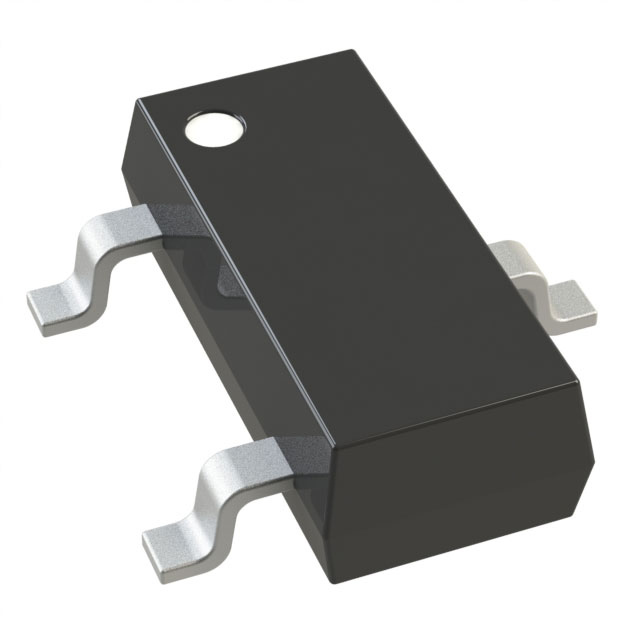
The PDTC144VT,215 is a pre-biased NPN bipolar junction transistor (BJT) manufactured by Nexperia USA Inc. in the TO-236AB surface mount package. This component is designed for general-purpose switching and amplification applications requiring a 50 V collector-emitter breakdown voltage with 100 mA maximum collector current and 250 mW power dissipation. The device is AEC-Q100 qualified for automotive applications and carries Active product status. Equivalent and substitute parts are necessary when the primary part is unavailable, when alternative package configurations are required for specific PCB layouts, or when design requirements permit operation within the electrical parameter ranges of functionally compatible alternatives.
Substiute Parts
Key Parameters
| Parameter | Value | Unit |
|---|---|---|
| Transistor Type | NPN - Pre-Biased | — |
| Collector Current (Ic) Maximum | 100 | mA |
| Collector-Emitter Breakdown Voltage (Vceo) | 50 | V |
| Power Dissipation Maximum | 250 | mW |
| Base Resistor (R1) | 47 | kOhms |
| Emitter-Base Resistor (R2) | 10 | kOhms |
| DC Current Gain (hFE) Minimum | 40 @ 5mA, 5V | — |
| Vce Saturation Maximum | 150 | mV @ 500µA, 10mA |
| Collector Cutoff Current (Icbo) | 1 | µA |
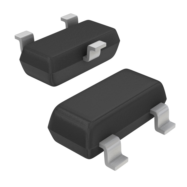
| Package Type | TO-236AB (SOT-23-3) | — |
| Mounting Type | Surface Mount | — |
| RoHS Status | ROHS3 Compliant | — |
| AEC-Q100 Qualification | Yes | — |
Substitute Part Grouping Explanation
Substitution of the PDTC144VT,215 is determined by electrical and mechanical compatibility within the following criteria:
Critical Parameters for Substitution:
- Transistor type must be NPN pre-biased
- Collector-emitter breakdown voltage must be 50 V or greater
- Maximum collector current must be 100 mA or greater
- Base resistor (R1) must be 47 kOhms
- Emitter-base resistor (R2) must be 10 kOhms (where applicable)
- Package must be surface mount in TO-236-3, SC-59, or SOT-23-3 configurations
- RoHS3 compliance required
Substitute parts are grouped into two categories:
-
Direct Electrical Equivalents with Identical Package (TO-236AB/SOT-23-3): DDTC144VCA-7-F and MMUN2213LT1G maintain the same package footprint and all critical resistor values, enabling direct PCB substitution without layout modification.
-
Functional Equivalents with Alternative Packages: DDTC144GUA-7-F (SOT-323), DDTC144TCA-7-F (SOT-23-3), DDTC144TUA-7-F (SOT-323), DDTC144TE-7-F (SOT-523), MUN2213T1G (SC-59), and RN1418(TE85L,F) (S-Mini) provide equivalent electrical performance but require PCB layout adjustment due to different package geometries. These parts maintain the 50 V breakdown voltage, 100 mA collector current, and surface mount technology.
Parameter Comparison
| Parameter | PDTC144VT,215 | DDTC144VCA-7-F | DDTC144TCA-7-F | DDTC144TUA-7-F | DDTC144GUA-7-F | DDTC144TE-7-F | MMUN2213LT1G | MUN2213T1G | RN1418(TE85L,F) |
|---|---|---|---|---|---|---|---|---|---|
| Manufacturer | Nexperia | Diodes Inc. | Diodes Inc. | Diodes Inc. | Diodes Inc. | Diodes Inc. | onsemi | onsemi | Toshiba |
| Transistor Type | NPN Pre-Biased | NPN Pre-Biased | NPN Pre-Biased | NPN Pre-Biased | NPN Pre-Biased | NPN Pre-Biased | NPN Pre-Biased | NPN Pre-Biased | NPN Pre-Biased |
| Ic (Max) | 100 mA | 100 mA | 100 mA | 100 mA | 100 mA | 100 mA | 100 mA | 100 mA | 100 mA |
| Vceo (Max) | 50 V | 50 V | 50 V | 50 V | 50 V | 50 V | 50 V | 50 V | 50 V |
| R1 (Base) | 47 kOhms | 47 kOhms | 47 kOhms | 47 kOhms | — | 47 kOhms | 47 kOhms | 47 kOhms | 47 kOhms |
| R2 (Emitter-Base) | 10 kOhms | 10 kOhms | — | — | 47 kOhms | — | 47 kOhms | 47 kOhms | 10 kOhms |
| hFE (Min) @ Ic, Vce | 40 @ 5mA, 5V | 33 @ 5mA, 5V | 100 @ 1mA, 5V | 100 @ 1mA, 5V | 68 @ 5mA, 5V | 100 @ 1mA, 5V | 80 @ 5mA, 10V | 80 @ 5mA, 10V | 50 @ 10mA, 5V |
| Vce Sat (Max) @ Ib, Ic | 150mV @ 500µA, 10mA | 300mV @ 500µA, 10mA | 300mV @ 250µA, 2.5mA | 300mV @ 250µA, 2.5mA | 300mV @ 500µA, 10mA | 300mV @ 250µA, 2.5mA | 250mV @ 300µA, 10mA | 250mV @ 300µA, 10mA | 300mV @ 250µA, 5mA |
| Icbo (Max) | 1 µA | 500 nA | 500 nA | 500 nA | 500 nA | 500 nA | 500 nA | 500 nA | 500 nA |
| Power (Max) | 250 mW | 200 mW | 200 mW | 200 mW | 200 mW | 150 mW | 246 mW | 338 mW | 200 mW |
| Frequency - Transition | — | 250 MHz | 250 MHz | 250 MHz | 250 MHz | 250 MHz | — | — | 250 MHz |
| Package | TO-236AB | SOT-23-3 | SOT-23-3 | SOT-323 | SOT-323 | SOT-523 | SOT-23-3 | SC-59 | S-Mini |
| RoHS Status | ROHS3 | ROHS3 | ROHS3 | ROHS3 | ROHS3 | ROHS3 | ROHS3 | ROHS3 | RoHS Compliant |
Engineering Selection Recommendations
Direct Substitution (No PCB Layout Changes Required):
DDTC144VCA-7-F and MMUN2213LT1G are the primary substitutes for the PDTC144VT,215. Both maintain the SOT-23-3 package footprint identical to the TO-236AB, enabling direct component replacement on existing PCB layouts. DDTC144VCA-7-F is manufactured by Diodes Incorporated and maintains the identical 47 kOhms base resistor and 10 kOhms emitter-base resistor configuration. MMUN2213LT1G is manufactured by onsemi and uses 47 kOhms for both base and emitter-base resistors, resulting in different DC current gain characteristics but maintaining functional compatibility within the 50 V, 100 mA operating envelope.
Alternative Package Substitutes (PCB Layout Modification Required):
When PCB layout permits alternative package geometries, the following substitutes provide equivalent electrical performance:
-
DDTC144TUA-7-F (Diodes Incorporated, SOT-323): Maintains 47 kOhms base resistor with superior inventory availability (69,400 units). Requires PCB footprint adjustment for the smaller SOT-323 package.
-
DDTC144TCA-7-F (Diodes Incorporated, SOT-23-3): Maintains identical package footprint to PDTC144VT,215 but uses different resistor configuration (47 kOhms base only). Inventory: 3,400 units.
-
MUN2213T1G (onsemi, SC-59): Provides higher power dissipation capability (338 mW) with identical resistor configuration (47 kOhms base and emitter-base). Suitable for applications requiring enhanced thermal performance.
-
RN1418(TE85L,F) (Toshiba, S-Mini): Maintains the 47 kOhms base and 10 kOhms emitter-base resistor configuration identical to the primary part. RoHS compliant with 250 MHz transition frequency.
Compliance and Qualification:
All substitute parts maintain ROHS3 compliance and Unlimited moisture sensitivity level (MSL 1). The PDTC144VT,215 carries AEC-Q100 automotive qualification. Substitute parts from Diodes Incorporated and onsemi are Active status products with equivalent reliability certifications. Selection should prioritize parts with matching resistor configurations when circuit biasing characteristics are critical to application performance.
Frequently Asked Questions (FAQ)
Q: Can DDTC144VCA-7-F be used as a direct replacement for PDTC144VT,215 without PCB modification?
A: Yes. DDTC144VCA-7-F is packaged in SOT-23-3, which is electrically and mechanically equivalent to the TO-236AB package of the PDTC144VT,215. Both parts maintain the 47 kOhms base resistor and 10 kOhms emitter-base resistor configuration. The component can be placed on the existing PCB footprint without layout changes.
Q: What is the difference between parts with R2 = 10 kOhms and R2 = 47 kOhms?
A: The emitter-base resistor (R2) value affects the DC current gain and switching characteristics of the pre-biased transistor. PDTC144VT,215 with R2 = 10 kOhms provides a minimum hFE of 40 at 5 mA collector current. Substitutes with R2 = 47 kOhms (such as MMUN2213LT1G) provide higher DC current gain (hFE minimum of 80 at 5 mA). Selection depends on whether the application circuit is designed for the specific gain characteristics of the original part.
Q: Are all substitute parts suitable for automotive applications?
A: The PDTC144VT,215 carries AEC-Q100 qualification for automotive use. Substitute parts from Diodes Incorporated, onsemi, and Toshiba are Active status products with equivalent reliability standards and ROHS3 compliance. However, automotive qualification status should be confirmed with the component manufacturer if the application requires explicit AEC-Q100 certification.
Q: What is the impact of different power dissipation ratings on substitution?
A: The PDTC144VT,215 is rated for 250 mW maximum power dissipation. Substitute parts range from 150 mW (DDTC144TE-7-F) to 338 mW (MUN2213T1G). Parts with lower power ratings (150 mW) may require thermal management review in high-current applications. Parts with higher power ratings provide additional thermal margin. Selection should ensure the substitute part's power rating meets or exceeds the application's thermal requirements.
Q: Can DDTC144TE-7-F be used if the application requires 250 mW power dissipation?
A: DDTC144TE-7-F is rated for 150 mW maximum power dissipation, which is lower than the PDTC144VT,215 specification of 250 mW. This part is suitable only if the application's actual power dissipation remains below 150 mW. Thermal analysis of the specific circuit is required to confirm compatibility.
Q: What package considerations apply when selecting alternative substitutes?
A: The PDTC144VT,215 uses the TO-236AB package (SOT-23-3 footprint). Direct substitutes maintaining this footprint include DDTC144VCA-7-F and MMUN2213LT1G, requiring no PCB layout changes. Alternative packages include SOT-323 (DDTC144TUA-7-F, DDTC144GUA-7-F), SOT-523 (DDTC144TE-7-F), SC-59 (MUN2213T1G), and S-Mini (RN1418). Each alternative package has different pin spacing and footprint dimensions, requiring PCB layout modification and verification of mechanical clearance.
Q: How do DC current gain differences affect circuit operation?
A: The PDTC144VT,215 specifies hFE minimum of 40 at 5 mA collector current and 5 V Vce. Substitutes range from hFE minimum of 33 to 100 depending on measurement conditions. Higher DC current gain results in faster switching and lower base drive requirements. If the circuit is designed for the specific gain of the original part, substitutes with significantly different hFE values may alter switching speed and power consumption characteristics. Circuit simulation or bench testing is recommended when substituting parts with hFE values differing by more than 25%.
Q: Are there inventory considerations when selecting substitutes?
A: Yes. Inventory levels vary significantly among substitutes. DDTC144TUA-7-F has the highest availability at 69,400 units, while RN1418(TE85L,F) has the lowest at 2,205 units. For high-volume production or long-term supply chain planning, parts with higher inventory levels provide greater availability assurance. However, inventory levels are subject to change and should be confirmed with the component supplier at the time of procurement.
Alternative Parts

SJ6012L2TP
Littelfuse Inc.
6 Alternative Parts

JMK107BBJ476MA-RE
Taiyo Yuden
10 Alternative Parts

GMK107BBJ475MA-T
Taiyo Yuden
5 Alternative Parts
SJ6020N2ARP
Littelfuse Inc.
3 Alternative Parts
SJ6025R2ATP
Littelfuse Inc.
4 Alternative Parts

2474-05L
API Delevan Inc.
1 Alternative Parts

4590R-684K
API Delevan Inc.
1 Alternative Parts

CM6560R-334
API Delevan Inc.
1 Alternative Parts

CM6460-104
API Delevan Inc.
1 Alternative Parts

5526-12
API Delevan Inc.
1 Alternative Parts