


Request Quote
(Ships tomorrow)
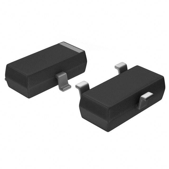
PDTC143XK,115 Pre-Biased NPN Transistor Equivalent & Substitute Parts
Part Overview
The PDTC143XK,115 is a pre-biased NPN bipolar junction transistor (BJT) manufactured by NXP USA Inc., designed for surface mount applications in the SOT-23-3 (TO-236-3, SC-59) package. This component integrates internal base and emitter resistors, enabling simplified circuit design for switching and amplification applications. The part is classified as obsolete, necessitating identification of functionally equivalent alternatives from active product lines to ensure design continuity and supply chain reliability.
Substiute Parts
Key Parameters
| Parameter | Value | Unit |
|---|---|---|
| Transistor Type | NPN - Pre-Biased | — |
| Maximum Collector Current (Ic) | 100 | mA |
| Collector-Emitter Breakdown Voltage (VCEO) | 50 | V |
| Base Resistor (R1) | 4.7 | kΩ |
| Emitter-Base Resistor (R2) | 10 | kΩ |
| DC Current Gain (hFE) @ Ic, Vce | 50 @ 10mA, 5V | — |
| Saturation Voltage (Vce sat) @ Ib, Ic | 100mV @ 500µA, 10mA | — |
| Collector Cutoff Current (ICBO) | 1 | µA |
| Maximum Power Dissipation | 250 | mW |
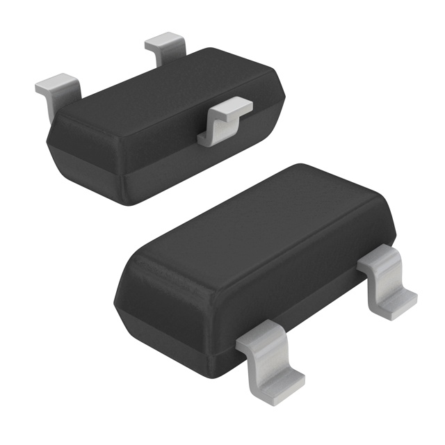
| Package Type | TO-236-3, SC-59, SOT-23-3 | — |
| Mounting Type | Surface Mount | — |
| RoHS Status | ROHS3 Compliant | — |
| Moisture Sensitivity Level (MSL) | 1 (Unlimited) | — |
Substitute Part Grouping Explanation
Substitution of the PDTC143XK,115 is determined by strict equivalence across the following critical parameters:
Mandatory Matching Criteria:
- Transistor type: NPN pre-biased configuration
- Maximum collector current: 100 mA
- Collector-emitter breakdown voltage: 50 V
- Base resistor (R1): 4.7 kΩ
- Emitter-base resistor (R2): 10 kΩ (for direct pin-compatible substitution)
- Package type: TO-236-3, SC-59, or SOT-23-3 surface mount
- RoHS3 compliance and MSL 1 rating
Acceptable Variation Parameters:
- DC current gain (hFE): Variations within application tolerance
- Saturation voltage (Vce sat): Variations within application tolerance
- Collector cutoff current (ICBO): Variations within application tolerance
- Maximum power dissipation: Equal or greater than 250 mW
- Transition frequency: Not specified for main part; higher values acceptable
Substitute parts meeting these criteria are functionally equivalent for direct replacement in the original circuit design without modification to PCB layout or component footprint.
Parameter Comparison
| Parameter | PDTC143XK,115 (NXP) | DDTC143XCA-7-F (Diodes) | DTC143XKAT146 (Rohm) | MMUN2217LT1G (onsemi) | MMUN2233LT1G (onsemi) | MUN2233T1G (onsemi) | NSVMUN2233T1G (onsemi) |
|---|---|---|---|---|---|---|---|
| Manufacturer | NXP USA Inc. | Diodes Incorporated | Rohm Semiconductor | onsemi | onsemi | onsemi | onsemi |
| Transistor Type | NPN - Pre-Biased | NPN - Pre-Biased | NPN - Pre-Biased | NPN - Pre-Biased | NPN - Pre-Biased | NPN - Pre-Biased | NPN - Pre-Biased |
| Ic (Max) | 100 mA | 100 mA | 100 mA | 100 mA | 100 mA | 100 mA | 100 mA |
| VCEO (Max) | 50 V | 50 V | 50 V | 50 V | 50 V | 50 V | 50 V |
| R1 (Base Resistor) | 4.7 kΩ | 4.7 kΩ | 4.7 kΩ | 4.7 kΩ | 4.7 kΩ | 4.7 kΩ | 4.7 kΩ |
| R2 (Emitter-Base Resistor) | 10 kΩ | 10 kΩ | 10 kΩ | 10 kΩ | 47 kΩ | 47 kΩ | 47 kΩ |
| hFE (Min) @ Ic, Vce | 50 @ 10mA, 5V | 30 @ 10mA, 5V | 30 @ 10mA, 5V | 35 @ 5mA, 10V | 80 @ 5mA, 10V | 80 @ 5mA, 10V | 80 @ 5mA, 10V |
| Vce Sat (Max) @ Ib, Ic | 100mV @ 500µA, 10mA | 300mV @ 500µA, 10mA | 300mV @ 500µA, 10mA | 250mV @ 1mA, 10mA | 250mV @ 300µA, 10mA | 250mV @ 300µA, 10mA | 250mV @ 1mA, 10mA |
| ICBO (Max) | 1 µA | 500 nA | 500 nA | 500 nA | 500 nA | 500 nA | 500 nA |
| Power (Max) | 250 mW | 200 mW | 200 mW | 246 mW | 246 mW | 338 mW | 230 mW |
| Package | TO-236-3, SC-59, SOT-23-3 | TO-236-3, SC-59, SOT-23-3 | TO-236-3, SC-59, SOT-23-3 | TO-236-3, SC-59, SOT-23-3 | TO-236-3, SC-59, SOT-23-3 | TO-236-3, SC-59, SOT-23-3 | TO-236-3, SC-59, SOT-23-3 |
| Product Status | Obsolete | Active | Active | Active | Active | Active | Active |
| RoHS Status | ROHS3 Compliant | ROHS3 Compliant | ROHS3 Compliant | ROHS3 Compliant | ROHS3 Compliant | ROHS3 Compliant | ROHS3 Compliant |
| MSL Rating | 1 (Unlimited) | 1 (Unlimited) | 1 (Unlimited) | 1 (Unlimited) | 1 (Unlimited) | 1 (Unlimited) | 1 (Unlimited) |
Engineering Selection Recommendations
Direct Pin-Compatible Substitutes (R2 = 10 kΩ):
The DDTC143XCA-7-F (Diodes Incorporated) and DTC143XKAT146 (Rohm Semiconductor) are direct functional equivalents with identical base and emitter resistor values (R1 = 4.7 kΩ, R2 = 10 kΩ). Both parts are in active production status, ensuring long-term supply availability. DDTC143XCA-7-F offers higher inventory levels (1,825 units) with active product status. DTC143XKAT146 provides the largest available inventory (2,405,200 units) and is recommended for high-volume applications requiring supply security.
Alternative Substitutes (R2 = 47 kΩ):
The onsemi parts MMUN2233LT1G, MUN2233T1G, and NSVMUN2233T1G feature an emitter-base resistor of 47 kΩ instead of 10 kΩ. These parts are functionally equivalent for applications where the higher emitter-base resistor value is acceptable. MMUN2233LT1G (460,600 units in stock) and MUN2233T1G (100,200 units) are recommended for applications tolerant of this resistor configuration. NSVMUN2233T1G is available with limited inventory (957 units).
Compliance and Certification:
All substitute parts maintain ROHS3 compliance and MSL 1 (unlimited moisture sensitivity) ratings, matching the original PDTC143XK,115 specifications. All parts carry EAR99 ECCN classification and REACH unaffected status, ensuring regulatory compliance across global markets.
Frequently Asked Questions (FAQ)
Q: Can DDTC143XCA-7-F directly replace PDTC143XK,115 without circuit modification?
A: Yes. DDTC143XCA-7-F is a direct functional equivalent with identical base resistor (4.7 kΩ) and emitter-base resistor (10 kΩ) values. The package type (TO-236-3, SC-59, SOT-23-3) and pin configuration are identical, enabling direct PCB substitution without design changes.
Q: What is the difference between parts with R2 = 10 kΩ and R2 = 47 kΩ?
A: The emitter-base resistor (R2) value affects the transistor's biasing characteristics and switching behavior. Parts with R2 = 10 kΩ (DDTC143XCA-7-F, DTC143XKAT146, MMUN2217LT1G) maintain identical biasing to the original PDTC143XK,115. Parts with R2 = 47 kΩ (MMUN2233LT1G, MUN2233T1G, NSVMUN2233T1G) provide different biasing and are suitable only for applications where this resistor configuration is acceptable.
Q: Are all substitute parts available in the same package?
A: Yes. All listed substitute parts are available in TO-236-3, SC-59, or SOT-23-3 surface mount packages. Package footprints are identical, ensuring compatibility with existing PCB designs. Verify specific supplier device package designation (SMT3, PG-SOT23, SOT-23-3, SC-59) when ordering to confirm exact packaging format.
Q: What is the product status significance for long-term supply?
A: The original PDTC143XK,115 is classified as obsolete, indicating discontinued production. All recommended substitute parts are in active production status, ensuring continued availability for new designs and production runs. DTC143XKAT146 (Rohm) and MMUN2233LT1G (onsemi) offer the highest inventory levels for supply security.
Q: Do all substitute parts meet the same compliance requirements?
A: Yes. All substitute parts are ROHS3 compliant with MSL 1 (unlimited) moisture sensitivity ratings, matching the original part's environmental and regulatory specifications. All parts carry EAR99 ECCN classification and REACH unaffected status for global market compliance.
Q: What is the significance of transition frequency (fT) specifications?
A: Transition frequency is specified for some substitute parts (BCR112E6327HTSA1: 140 MHz; DDTC143TCA-7-F, DDTC143XCA-7-F, DTC143XKAT146: 250 MHz) but not for the original PDTC143XK,115. Higher transition frequency indicates improved high-frequency performance. For applications operating below specified frequencies, this parameter does not affect substitution validity.
Q: How do saturation voltage differences affect circuit performance?
A: The original PDTC143XK,115 specifies Vce sat = 100 mV @ 500 µA, 10 mA. Most substitute parts specify 250–300 mV under similar conditions. For switching applications, higher saturation voltage results in slightly increased power dissipation. Verify that circuit design tolerates the substitute part's saturation voltage specification before implementation.
Alternative Parts

SJ6012L2TP
Littelfuse Inc.
6 Alternative Parts

JMK107BBJ476MA-RE
Taiyo Yuden
10 Alternative Parts

GMK107BBJ475MA-T
Taiyo Yuden
5 Alternative Parts
SJ6020N2ARP
Littelfuse Inc.
3 Alternative Parts
SJ6025R2ATP
Littelfuse Inc.
4 Alternative Parts

2474-05L
API Delevan Inc.
1 Alternative Parts

4590R-684K
API Delevan Inc.
1 Alternative Parts

CM6560R-334
API Delevan Inc.
1 Alternative Parts

CM6460-104
API Delevan Inc.
1 Alternative Parts

5526-12
API Delevan Inc.
1 Alternative Parts