


Request Quote
(Ships tomorrow)
PDTC124TT,215 Equivalent & Substitute Parts
Part Overview
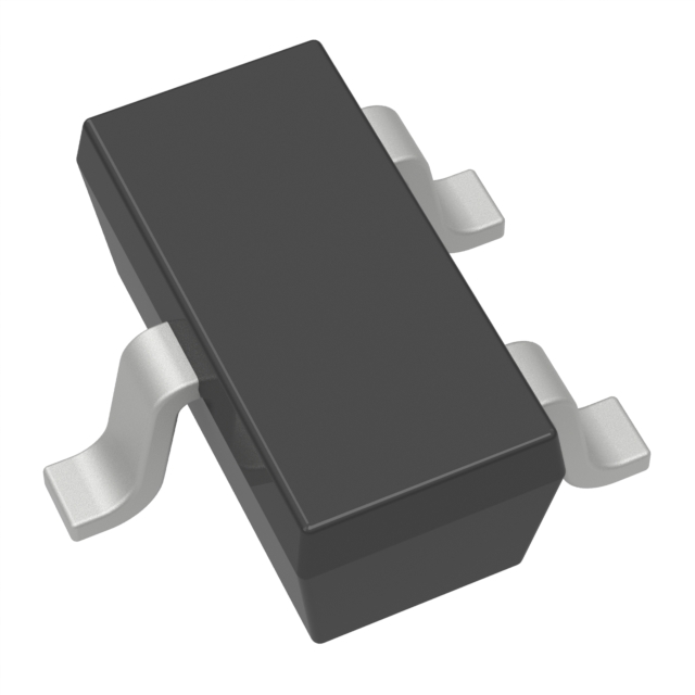
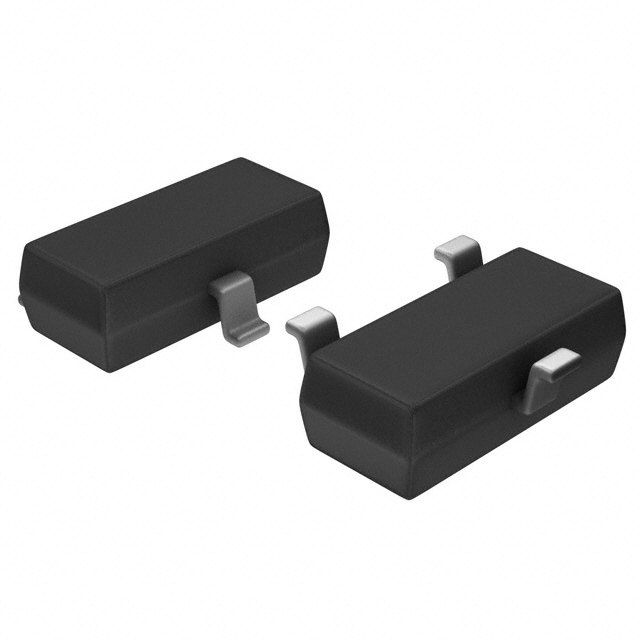
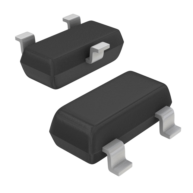
The PDTC124TT,215 is a pre-biased NPN bipolar junction transistor (BJT) manufactured by Nexperia USA Inc. in TO-236AB surface mount packaging. This component is classified as an active product and is designed for general-purpose switching and amplification applications requiring a 50 V collector-emitter breakdown voltage with 100 mA maximum collector current. The device integrates an internal 22 kOhm base resistor for simplified circuit design and reduced component count.
Equivalent and substitute parts are necessary when the primary part becomes unavailable, when alternative packaging formats are required for manufacturing compatibility, or when design revisions necessitate component sourcing from multiple suppliers. This reference provides direct substitutes based on electrical and mechanical parameter compatibility.
Substiute Parts
Key Parameters
| Parameter | Value | Unit |
|---|---|---|
| Transistor Type | NPN - Pre-Biased | — |
| Collector-Emitter Breakdown Voltage (Max) | 50 | V |
| Collector Current (Max) | 100 | mA |
| Power Dissipation (Max) | 250 | mW |
| Base Resistor (R1) | 22 | kOhms |
| DC Current Gain (hFE Min) @ Ic, Vce | 100 @ 1mA, 5V | — |
| Vce Saturation (Max) @ Ib, Ic | 150mV @ 500µA, 10mA | — |
| Collector Cutoff Current (Max) | 1 | µA |
| Mounting Type | Surface Mount | — |
| Package / Case | TO-236-3, SC-59, SOT-23-3 | — |
| RoHS Status | ROHS3 Compliant | — |
| Moisture Sensitivity Level (MSL) | 1 (Unlimited) | — |
| Grade | Automotive | — |
| Qualification | AEC-Q100 | — |
Substitute Part Grouping Explanation
Substitution compatibility for the PDTC124TT,215 is determined by the following critical parameters:
Electrical Compatibility Requirements:
- Collector-Emitter Breakdown Voltage: 50 V (minimum requirement)
- Collector Current Rating: 100 mA (minimum requirement)
- Transistor Type: NPN - Pre-Biased (mandatory)
- Base Resistor Value: 22 kOhms (preferred for direct pin-compatible substitution)
- DC Current Gain (hFE): 100 @ 1mA, 5V (preferred specification)
- Vce Saturation: ≤ 300mV @ specified test conditions (acceptable range)
Mechanical Compatibility Requirements:
- Mounting Type: Surface Mount (mandatory)
- Package Format: TO-236-3, SC-59, or SOT-23-3 (acceptable variants)
- Lead Configuration: 3-pin (mandatory)
Compliance Requirements:
- RoHS3 Compliance (mandatory for new designs)
- Moisture Sensitivity Level: 1 (Unlimited) (preferred)
- REACH Unaffected status (preferred)
Substitute parts are grouped into two categories:
Category A - Direct Electrical & Package Equivalents: Parts with identical base resistor value (22 kOhms), matching DC current gain specification, and compatible package formats. These parts provide direct functional replacement with minimal circuit redesign.
Category B - Functional Equivalents with Parameter Variations: Parts with alternative base resistor values, different DC current gain specifications, or enhanced power ratings. These parts require circuit verification but maintain core electrical functionality within acceptable operating ranges.
Parameter Comparison
| Part Number | Manufacturer | Vce Breakdown (V) | Ic Max (mA) | Power Max (mW) | Base Resistor (kOhms) | hFE Min @ Ic, Vce | Vce Sat Max (mV) | Package | Product Status |
|---|---|---|---|---|---|---|---|---|---|
| PDTC124TT,215 | Nexperia USA Inc. | 50 | 100 | 250 | 22 | 100 @ 1mA, 5V | 150 @ 500µA, 10mA | TO-236AB | Active |
| DDTC124TCA-7-F | Diodes Incorporated | 50 | 100 | 200 | 22 | 100 @ 1mA, 5V | 300 @ 500µA, 5mA | SOT-23-3 | Active |
| DTC124TKAT146 | Rohm Semiconductor | 50 | 100 | 200 | 22 | 100 @ 1mA, 5V | 300 @ 500µA, 5mA | SMT3 | Not For New Designs |
| DTC114TKAT146 | Rohm Semiconductor | 50 | 100 | 200 | 10 | 100 @ 1mA, 5V | 300 @ 1mA, 10mA | SMT3 | Active |
| DTC143TKAT146 | Rohm Semiconductor | 50 | 100 | 200 | 4.7 | 100 @ 1mA, 5V | 150 @ 250µA, 5mA | SMT3 | Active |
| DDTC124GE-7-F | Diodes Incorporated | 50 | 100 | 150 | 22 (R2) | 56 @ 5mA, 5V | 300 @ 500µA, 10mA | SOT-523 | Active |
| DTD114GKT146 | Rohm Semiconductor | 50 | 500 | 200 | 10 (R2) | 56 @ 50mA, 5V | 300 @ 2.5mA, 50mA | SMT3 | Active |
| MMUN2212LT1G | onsemi | 50 | 100 | 246 | 22 (R1 & R2) | 60 @ 5mA, 10V | 250 @ 300µA, 10mA | SOT-23-3 | Active |
| MMUN2234LT1G | onsemi | 50 | 100 | 246 | 22 (R1), 47 (R2) | 80 @ 5mA, 10V | 250 @ 1mA, 10mA | SOT-23-3 | Active |
| MUN2212T1G | onsemi | 50 | 100 | 338 | 22 (R1 & R2) | 60 @ 5mA, 10V | 250 @ 300µA, 10mA | SC-59 | Active |
| RN1412TE85LF | Toshiba Semiconductor and Storage | 50 | 100 | 200 | 22 | 120 @ 1mA, 5V | 300 @ 250µA, 5mA | S-Mini | Active |
Engineering Selection Recommendations
Primary Substitutes (Category A - Direct Equivalents):
The following parts provide direct functional replacement for the PDTC124TT,215 with minimal circuit redesign:
-
DDTC124TCA-7-F (Diodes Incorporated): Maintains 22 kOhm base resistor, 100 mA collector current, and 100 hFE specification. Active product status with ROHS3 compliance. SOT-23-3 package format is mechanically compatible with TO-236AB footprint. Vce saturation specification of 300mV is within acceptable operating range.
-
MMUN2212LT1G (onsemi): Dual-resistor configuration (22 kOhm R1 and R2) provides equivalent biasing network. 100 mA collector current and 50 V breakdown voltage match primary specifications. Active product with ROHS3 compliance and unlimited MSL rating. SOT-23-3 package compatible with existing PCB layouts.
-
RN1412TE85LF (Toshiba Semiconductor and Storage): Identical 22 kOhm base resistor and 100 mA collector current rating. Enhanced hFE specification of 120 @ 1mA, 5V provides improved gain margin. Active product with RoHS compliance. S-Mini package format compatible with TO-236-3 footprint specifications.
Secondary Substitutes (Category B - Functional Equivalents):
The following parts maintain core electrical functionality with parameter variations requiring circuit verification:
-
DTC114TKAT146 (Rohm Semiconductor): Reduced base resistor value of 10 kOhms increases base drive sensitivity. Maintains 100 mA collector current and 50 V breakdown voltage. Active product status. SMT3 package compatible with TO-236-3 footprint. Suitable for applications requiring faster switching response.
-
DTC143TKAT146 (Rohm Semiconductor): Significantly reduced base resistor value of 4.7 kOhms provides maximum base drive. Maintains 100 mA collector current and 50 V breakdown voltage. Active product status. Improved Vce saturation of 150mV @ 250µA, 5mA. Recommended for high-speed switching applications.
-
MMUN2234LT1G (onsemi): Asymmetric resistor configuration (22 kOhm R1, 47 kOhm R2) provides modified biasing characteristics. Maintains 100 mA collector current and 50 V breakdown voltage. Active product with ROHS3 compliance. Enhanced hFE of 80 @ 5mA, 10V. SOT-23-3 package compatible.
Not Recommended for New Designs:
- DTC124TKAT146 (Rohm Semiconductor): Product status is "Not For New Designs." Although electrically equivalent to the primary part, this component should not be selected for new circuit development. Existing designs may continue to use this part for continuity purposes.
Higher Current Alternative:
- DTD114GKT146 (Rohm Semiconductor): Rated for 500 mA collector current with 50 V breakdown voltage. Suitable only for applications requiring higher current handling than the standard 100 mA specification. Not a direct substitute but available for design flexibility in higher-power applications.
Frequently Asked Questions (FAQ)
Q: Can DDTC124TCA-7-F directly replace PDTC124TT,215 without circuit modification?
A: Yes. Both parts maintain identical collector-emitter breakdown voltage (50 V), collector current rating (100 mA), base resistor value (22 kOhms), and DC current gain specification (100 @ 1mA, 5V). The SOT-23-3 package is mechanically compatible with TO-236AB footprints. Vce saturation specification differs slightly (300mV vs. 150mV), but both values are within acceptable operating ranges for standard switching applications.
Q: What is the difference between parts with R1 and R2 resistor designations?
A: R1 designates a base resistor configuration, while R2 designates an emitter-base resistor configuration. Both provide internal biasing networks for pre-biased transistor operation. Parts with R1 (such as PDTC124TT,215 and DDTC124TCA-7-F) are functionally equivalent to parts with R2 (such as DDTC124GE-7-F) when the resistor values are identical. Circuit behavior may differ slightly due to different biasing topologies; verification is recommended for critical applications.
Q: Why do some substitute parts have lower power ratings than the primary part?
A: Power dissipation rating depends on package thermal characteristics and die size. The PDTC124TT,215 is rated for 250 mW in TO-236AB packaging. Substitute parts in smaller packages (such as SOT-523 at 150 mW) have reduced thermal dissipation capability. For applications operating near maximum power limits, verify that the substitute part's power rating is sufficient for the intended duty cycle and ambient temperature conditions.
Q: Are all listed substitute parts ROHS3 compliant?
A: All substitute parts listed in this reference are ROHS3 compliant or RoHS compliant. The primary part PDTC124TT,215 is ROHS3 compliant. Verify compliance status with the specific supplier for the selected substitute part, as compliance certifications may vary by manufacturing date and supplier region.
Q: Can DTC114TKAT146 be used as a substitute despite its "Not For New Designs" status?
A: DTC114TKAT146 is electrically equivalent to PDTC124TT,215 and may be used in existing designs for continuity or repair purposes. However, this part should not be selected for new circuit development. For new designs, select from parts with "Active" product status, such as DDTC124TCA-7-F, MMUN2212LT1G, or RN1412TE85LF.
Q: What is the significance of the base resistor value difference between DTC143TKAT146 (4.7 kOhms) and PDTC124TT,215 (22 kOhms)?
A: Lower base resistor values increase base drive current for a given input voltage, resulting in faster transistor switching and lower saturation voltage. DTC143TKAT146 with 4.7 kOhms provides approximately 4.7 times greater base drive than PDTC124TT,215. This part is suitable for high-speed switching applications but may increase power dissipation in the base circuit. Circuit redesign and testing are required before substitution.
Q: Is the onsemi MUN2212T1G suitable for space-constrained PCB layouts?
A: MUN2212T1G uses SC-59 package format, which is physically larger than the TO-236AB or SOT-23-3 packages used by the primary part and most substitutes. SC-59 is not recommended for space-constrained applications. For compact layouts, select DDTC124TCA-7-F, MMUN2212LT1G, or MMUN2234LT1G, which use SOT-23-3 packaging.
Q: What is the collector cutoff current specification, and why does it vary among substitute parts?
A: Collector cutoff current (ICBO) is the leakage current flowing from collector to base when the transistor is in the off state. The primary part PDTC124TT,215 specifies 1 µA maximum. Most substitute parts specify 500 nA maximum, indicating lower leakage. Lower leakage current improves off-state performance and reduces power consumption in standby conditions. This variation is acceptable for most applications.
Q: Can DTD114GKT146 be used in circuits designed for 100 mA maximum collector current?
A: DTD114GKT146 is rated for 500 mA collector current and is not a direct substitute for 100 mA applications. Although the part can operate at 100 mA, its internal characteristics (lower hFE of 56 @ 50mA, 5V vs. 100 @ 1mA, 5V) and different resistor configuration (10 kOhm R2 emitter-base) make it unsuitable without circuit redesign. Use DTD114GKT146 only in applications requiring higher current capability.
Alternative Parts

SJ6012L2TP
Littelfuse Inc.
6 Alternative Parts

JMK107BBJ476MA-RE
Taiyo Yuden
10 Alternative Parts

GMK107BBJ475MA-T
Taiyo Yuden
5 Alternative Parts
SJ6020N2ARP
Littelfuse Inc.
3 Alternative Parts
SJ6025R2ATP
Littelfuse Inc.
4 Alternative Parts

2474-05L
API Delevan Inc.
1 Alternative Parts

4590R-684K
API Delevan Inc.
1 Alternative Parts

CM6560R-334
API Delevan Inc.
1 Alternative Parts

CM6460-104
API Delevan Inc.
1 Alternative Parts

5526-12
API Delevan Inc.
1 Alternative Parts