


Request Quote
(Ships tomorrow)
PDTC115TE,115 Pre-Biased NPN Transistor Equivalent & Substitute Parts
Part Overview
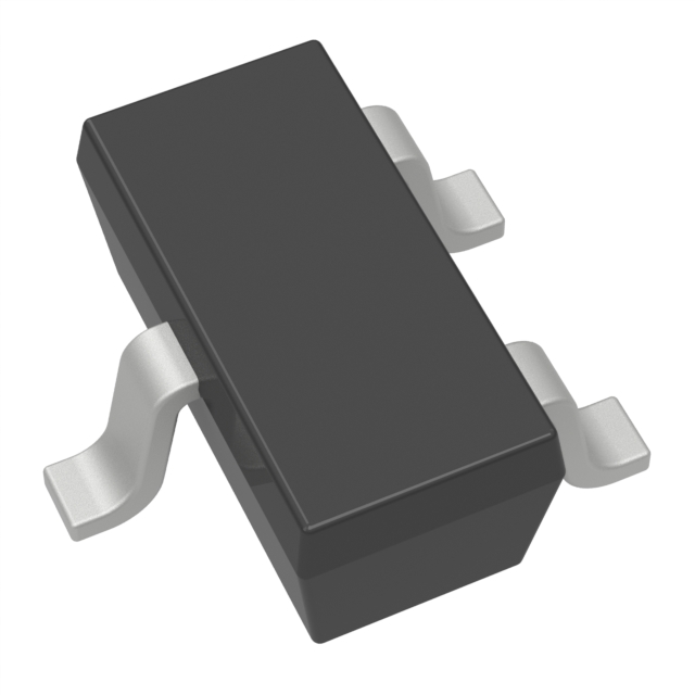
The PDTC115TE,115 is a pre-biased NPN bipolar junction transistor manufactured by NXP USA Inc., designed for surface mount applications in the SC-75 (SOT-416) package. This component operates at a maximum collector-emitter breakdown voltage of 50 V with a maximum collector current of 100 mA and maximum power dissipation of 150 mW. The device features an integrated base resistor of 100 kOhms and is classified as obsolete. Due to its obsolete product status, equivalent and substitute parts from active manufacturers are necessary to maintain design continuity and ensure long-term component availability for new production and field replacements.
Substiute Parts
Key Parameters
| Parameter | Value | Unit |
|---|---|---|
| Transistor Type | NPN - Pre-Biased | — |
| Current - Collector (Ic) Max | 100 | mA |
| Voltage - Collector Emitter Breakdown (Max) | 50 | V |
| Resistor - Base (R1) | 100 | kOhms |
| DC Current Gain (hFE) Min @ Ic, Vce | 100 @ 1mA, 5V | — |
| Vce Saturation (Max) @ Ib, Ic | 150 | mV @ 250µA, 5mA |
| Current - Collector Cutoff (Max) | 1 | µA |
| Power - Max | 150 | mW |
| Package / Case | SC-75, SOT-416 | — |
| Mounting Type | Surface Mount | — |
| RoHS Status | ROHS3 Compliant | — |
| Moisture Sensitivity Level (MSL) | 1 (Unlimited) | — |
Substitute Part Grouping Explanation
Substitution of the PDTC115TE,115 is determined by the following critical electrical and mechanical parameters:
Electrical Compatibility Criteria:
- Maximum collector current (Ic Max): 100 mA minimum
- Collector-emitter breakdown voltage (Vce Breakdown): 50 V minimum
- Base resistor value (R1): 100 kOhms (primary criterion for pre-biased configuration)
- DC current gain (hFE): 100 minimum at specified test conditions
- Vce saturation: 150 mV maximum at specified bias conditions
- Power dissipation: 150 mW minimum
Mechanical Compatibility Criteria:
- Surface mount technology
- Package compatibility: SC-75 (SOT-416) or equivalent footprint packages
- Moisture sensitivity level: MSL 1 (Unlimited)
- RoHS3 compliance preferred for regulatory alignment
Substitute parts are grouped into two categories:
Category A - Direct Package Equivalents (SC-75/SOT-416): Parts maintaining identical or pin-compatible package geometry, enabling direct PCB footprint replacement without layout modification.
Category B - Alternative Package Substitutes: Parts with different package types (SOT-523, EMT3, SOT-883, DFN, TO-236AB, SOT-323) that require PCB layout redesign but maintain electrical parameter compatibility within specified tolerances.
Parameter Comparison
| Part Number | Manufacturer | Ic Max (mA) | Vce Breakdown (V) | R1 (kOhms) | hFE Min @ Ic, Vce | Vce Sat Max (mV) | Power Max (mW) | Package | Product Status |
|---|---|---|---|---|---|---|---|---|---|
| PDTC115TE,115 | NXP USA Inc. | 100 | 50 | 100 | 100 @ 1mA, 5V | 150 | 150 | SC-75, SOT-416 | Obsolete |
| DDTC115GE-7 | Diodes Incorporated | 100 | 50 | 100 (R2) | 82 @ 5mA, 5V | 300 | 150 | SOT-523 | Discontinued at DiGi Electronics |
| DTC114TETL | Rohm Semiconductor | 100 | 50 | 10 | 100 @ 1mA, 5V | 300 | 150 | SC-75, SOT-416 | Active |
| DTC115EET1G | onsemi | 100 | 50 | 100 | 80 @ 5mA, 10V | 250 | 200 | SC-75, SOT-416 | Active |
| DTC115EETL | Rohm Semiconductor | 20 | 50 | 100 | 82 @ 5mA, 5V | 300 | 150 | SC-75, SOT-416 | Active |
| DTC143TETL | Rohm Semiconductor | 100 | 50 | 4.7 | 100 @ 1mA, 5V | 150 | 150 | SC-75, SOT-416 | Active |
| PDTC115TM,315 | Nexperia USA Inc. | 100 | 50 | 100 | 100 @ 1mA, 5V | 150 | 250 | SC-101, SOT-883 | Active |
| PDTC115TMB,315 | Nexperia USA Inc. | 100 | 50 | 100 | 100 @ 1mA, 5V | 150 | 250 | 3-XFDFN | Active |
| PDTC115TT,215 | Nexperia USA Inc. | 100 | 50 | 100 | 100 @ 1mA, 5V | 150 | 250 | TO-236-3, SC-59, SOT-23-3 | Active |
| PDTC115TU,115 | Nexperia USA Inc. | 100 | 50 | 100 | 100 @ 1mA, 5V | 150 | 200 | SC-70, SOT-323 | Active |
Engineering Selection Recommendations
Primary Recommendation - Direct Package Replacement:
DTC115EET1G (onsemi) is the preferred direct substitute for PDTC115TE,115. This part maintains identical SC-75 (SOT-416) package geometry, enabling direct PCB footprint replacement without layout modification. The device is in active production status with robust inventory availability (2215 Pcs). Electrical parameters are within acceptable tolerance: 100 mA collector current, 50 V breakdown voltage, 100 kOhms base resistor, and 200 mW power rating (exceeds original 150 mW specification). RoHS3 compliance and MSL 1 rating match the original component specifications.
Secondary Recommendation - Same Package Family:
PDTC115TU,115 (Nexperia USA Inc.) provides an alternative within the Nexperia product family. This part maintains the 100 kOhms base resistor and identical electrical performance (100 mA, 50 V, 100 @ 1mA hFE). The SC-70 (SOT-323) package differs from the original SC-75, requiring PCB layout redesign. The device carries AEC-Q100 automotive qualification and active production status with extensive inventory (300,300 Pcs). Power rating of 200 mW exceeds the original specification.
Alternative for Current-Limited Applications:
DTC115EETL (Rohm Semiconductor) is suitable only for applications where collector current does not exceed 20 mA. This part maintains the SC-75 package and 100 kOhms base resistor but specifies a maximum collector current of 20 mA, representing a significant electrical limitation compared to the original 100 mA specification. Selection of this part requires verification that circuit design does not demand the full 100 mA capability.
Not Recommended:
DDTC115GE-7 (Diodes Incorporated) is discontinued at DiGi Electronics and carries non-compliant RoHS status, making it unsuitable for new designs requiring regulatory compliance.
DTC114TETL (Rohm Semiconductor) features a 10 kOhms base resistor, deviating from the original 100 kOhms specification. This parameter change alters the pre-biased transistor's switching characteristics and bias point, requiring circuit re-evaluation.
DTC143TETL (Rohm Semiconductor) features a 4.7 kOhms base resistor, representing a significant deviation from the original 100 kOhms specification and altering circuit behavior.
Frequently Asked Questions (FAQ)
Q1: Can DTC115EET1G directly replace PDTC115TE,115 without PCB modification?
A: Yes. DTC115EET1G maintains identical SC-75 (SOT-416) package geometry and pin configuration, enabling direct PCB footprint replacement. Electrical parameters are compatible within specified tolerances. No layout redesign is required.
Q2: What is the significance of the base resistor (R1) value in pre-biased transistor selection?
A: The base resistor value determines the transistor's bias point and switching characteristics. The PDTC115TE,115 specifies 100 kOhms. Substitute parts must maintain this value to preserve circuit behavior. Parts with different R1 values (such as DTC114TETL at 10 kOhms or DTC143TETL at 4.7 kOhms) alter the bias network and require circuit re-evaluation.
Q3: Why is PDTC115TU,115 listed as an alternative if it uses a different package?
A: PDTC115TU,115 maintains all critical electrical parameters (100 mA, 50 V, 100 kOhms R1, 100 @ 1mA hFE) and is in active production with extensive inventory. The SC-70 (SOT-323) package differs from SC-75, requiring PCB layout redesign. This part is recommended only when layout modification is feasible and the smaller package size provides design benefits.
Q4: Can DTC115EETL be used as a direct substitute?
A: DTC115EETL is not suitable for applications requiring the full 100 mA collector current specification. This part limits maximum collector current to 20 mA. Selection requires verification that circuit design operates within this reduced current range. If the application demands 100 mA capability, this part is not compatible.
Q5: What does "RoHS3 Compliant" mean for component selection?
A: RoHS3 compliance indicates the component meets Restriction of Hazardous Substances Directive requirements, restricting lead, cadmium, mercury, and other hazardous materials. For new designs and applications subject to regulatory requirements, RoHS3-compliant substitutes are mandatory. DDTC115GE-7, which is RoHS non-compliant, is unsuitable for such applications.
Q6: How does power rating affect substitute part selection?
A: The original PDTC115TE,115 specifies 150 mW maximum power dissipation. Substitute parts with equal or higher power ratings (such as DTC115EET1G at 200 mW or PDTC115TM,315 at 250 mW) are acceptable and provide additional thermal margin. Parts with lower power ratings are not suitable unless circuit design guarantees power dissipation remains below the specified limit.
Q7: What is the difference between Ic Max and the actual operating current in circuit design?
A: Ic Max (100 mA for the original part) represents the absolute maximum collector current the transistor can safely conduct. Circuit design must ensure actual operating current remains below this limit with appropriate safety margin. DTC115EETL, with Ic Max of only 20 mA, cannot be used in circuits designed for 100 mA operation.
Q8: Are Nexperia PDTC115 variants (TM,315; TMB,315; TT,215; TU,115) interchangeable?
A: All Nexperia PDTC115 variants maintain identical electrical specifications (100 mA, 50 V, 100 kOhms R1, 100 @ 1mA hFE, 150 mV Vce Sat). They differ only in package type and power rating. Selection depends on PCB layout requirements and thermal design. Direct package replacement is possible only between parts using the same package type.
Q9: What does "Discontinued at DiGi Electronics" mean for DDTC115GE-7?
A: This status indicates the part is no longer actively stocked or supported by the distributor. While the component may exist in legacy inventory, procurement for new production is unreliable. Additionally, DDTC115GE-7 carries non-compliant RoHS status, making it unsuitable for designs requiring regulatory compliance. This part should not be selected for new designs.
Q10: Can substitute parts with different Vce saturation values be used interchangeably?
A: Vce saturation affects switching speed and power dissipation in saturated operation. The original part specifies 150 mV maximum. Substitutes with higher Vce saturation (such as DTC115EET1G at 250 mV or DTC115EETL at 300 mV) dissipate more power in saturation and switch more slowly. For applications sensitive to switching speed or power dissipation, these differences may be significant. Circuit performance should be verified if Vce saturation differs substantially from the original specification.
Alternative Parts

SJ6012L2TP
Littelfuse Inc.
6 Alternative Parts

JMK107BBJ476MA-RE
Taiyo Yuden
10 Alternative Parts

GMK107BBJ475MA-T
Taiyo Yuden
5 Alternative Parts
SJ6020N2ARP
Littelfuse Inc.
3 Alternative Parts
SJ6025R2ATP
Littelfuse Inc.
4 Alternative Parts

2474-05L
API Delevan Inc.
1 Alternative Parts

4590R-684K
API Delevan Inc.
1 Alternative Parts

CM6560R-334
API Delevan Inc.
1 Alternative Parts

CM6460-104
API Delevan Inc.
1 Alternative Parts

5526-12
API Delevan Inc.
1 Alternative Parts