


Request Quote
(Ships tomorrow)
PDTA114TK,115 Pre-Biased PNP Transistor Equivalent & Substitute Parts
Part Overview
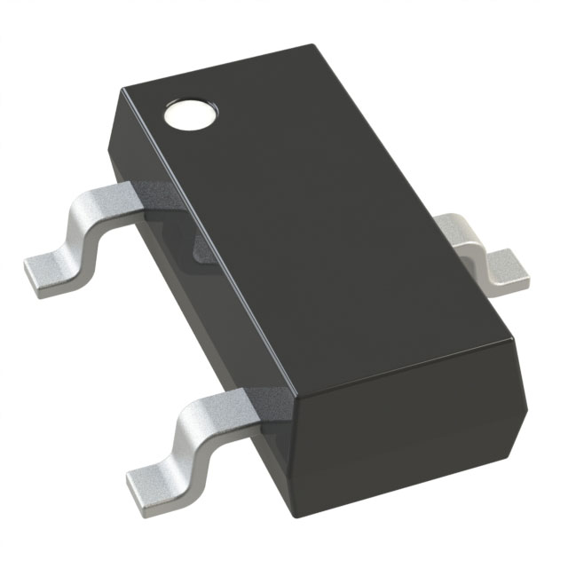
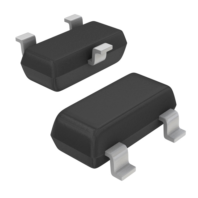
The PDTA114TK,115 is a pre-biased PNP bipolar junction transistor (BJT) manufactured by NXP USA Inc., designed for surface mount applications in the SMT3 package. This component operates at 50 V collector-emitter breakdown voltage with a maximum collector current of 100 mA and 250 mW power dissipation. The device features an integrated 10 kOhm base resistor (R1) for simplified circuit design.
The PDTA114TK,115 is classified as obsolete. Identifying equivalent and substitute parts is necessary to maintain design continuity, ensure supply chain availability, and support ongoing production requirements. Active alternatives from manufacturers including Diodes Incorporated, Micro Commercial Co, and Rohm Semiconductor provide functionally compatible solutions with enhanced availability and active product status.
Substiute Parts
Key Parameters
| Parameter | Value | Unit |
|---|---|---|
| Transistor Type | PNP - Pre-Biased | — |
| Current - Collector (Ic) Max | 100 | mA |
| Voltage - Collector Emitter Breakdown (Max) | 50 | V |
| Resistor - Base (R1) | 10 | kOhms |
| DC Current Gain (hFE) Min @ Ic, Vce | 200 @ 1mA, 5V | — |
| Vce Saturation (Max) @ Ib, Ic | 150 @ 500µA, 10mA | mV |
| Current - Collector Cutoff (Max) | 1 | µA |
| Power - Max | 250 | mW |
| Package / Case | TO-236-3, SC-59, SOT-23-3 | — |
| Mounting Type | Surface Mount | — |
| RoHS Status | ROHS3 Compliant | — |
| Moisture Sensitivity Level (MSL) | 1 (Unlimited) | — |
Substitute Part Grouping Explanation
Substitution of the PDTA114TK,115 is determined by strict alignment of the following critical parameters:
Primary Substitution Criteria:
- Transistor Type: PNP - Pre-Biased
- Collector-Emitter Breakdown Voltage: 50 V
- Maximum Collector Current: 100 mA
- Package / Case: TO-236-3, SC-59, SOT-23-3 (surface mount)
- Base Resistor (R1): 10 kOhms
Secondary Compatibility Factors:
- Power dissipation rating (minimum 200 mW acceptable)
- DC Current Gain (hFE) characteristics
- Vce Saturation voltage
- Collector cutoff current (ICBO)
Substitute parts are grouped into two categories:
Category A - Direct Equivalents (R1 = 10 kOhms): DDTA114ECA-7-F, DDTA114GCA-7-F, DDTA114TCA-7-F, DTA114ECA-TP, DTA114ECAT116, DTA114TCA-TP, DTA114TKAT146
These parts maintain the 10 kOhm base resistor specification, ensuring circuit behavior identical to the original PDTA114TK,115 in applications where the base resistor value is critical.
Category B - Functional Alternatives (Different R1 Values): DDTA123ECA-7-F (R1 = 2.2 kOhms), DDTA124ECA-7-F (R1 = 22 kOhms), DDTA143ECA-7-F (R1 = 4.7 kOhms)
These parts share the same voltage, current, and package specifications but feature different integrated base resistor values. Selection requires circuit-level analysis to confirm compatibility with the intended application.
Parameter Comparison
| Part Number | Manufacturer | Product Status | Ic Max (mA) | Vce Breakdown (V) | R1 (kOhms) | hFE Min @ Ic, Vce | Vce Sat Max (mV) | Power Max (mW) | Package |
|---|---|---|---|---|---|---|---|---|---|
| PDTA114TK,115 | NXP USA Inc. | Obsolete | 100 | 50 | 10 | 200 @ 1mA, 5V | 150 @ 500µA, 10mA | 250 | SMT3 |
| DDTA114ECA-7-F | Diodes Incorporated | Active | 100 | 50 | 10 | 30 @ 5mA, 5V | 300 @ 500µA, 10mA | 200 | SOT-23-3 |
| DDTA114GCA-7-F | Diodes Incorporated | Active | 100 | 50 | — | 30 @ 5mA, 5V | 300 @ 500µA, 10mA | 200 | SOT-23-3 |
| DDTA114TCA-7-F | Diodes Incorporated | Active | 100 | 50 | 10 | 100 @ 1mA, 5V | 300 @ 100µA, 1mA | 200 | SOT-23-3 |
| DDTA123ECA-7-F | Diodes Incorporated | Active | 100 | 50 | 2.2 | 20 @ 20mA, 5V | 300 @ 500µA, 10mA | 200 | SOT-23-3 |
| DDTA124ECA-7-F | Diodes Incorporated | Active | 100 | 50 | 22 | 56 @ 5mA, 5V | 300 @ 500µA, 10mA | 200 | SOT-23-3 |
| DDTA143ECA-7-F | Diodes Incorporated | Active | 100 | 50 | 4.7 | 20 @ 10mA, 5V | 300 @ 500µA, 10mA | 200 | SOT-23-3 |
| DTA114ECA-TP | Micro Commercial Co | Active | 100 | 50 | 10 | 30 @ 5mA, 5V | 300 @ 500µA, 10mA | 200 | SOT-23 |
| DTA114ECAT116 | Rohm Semiconductor | Active | 50 | 50 | 10 | 30 @ 5mA, 5V | 300 @ 500µA, 10mA | 200 | SST3 |
| DTA114TCA-TP | Micro Commercial Co | Active | 100 | 50 | 10 | 100 @ 1mA, 5V | 300 @ 1mA, 10mA | 200 | SOT-23 |
| DTA114TKAT146 | Rohm Semiconductor | Active | 100 | 50 | 10 | 100 @ 1mA, 5V | 300 @ 1mA, 10mA | 200 | SMT3 |
Engineering Selection Recommendations
For Direct Replacement (Identical Circuit Behavior):
Select DDTA114TCA-7-F, DTA114TCA-TP, or DTA114TKAT146 when the application requires matching DC current gain characteristics (hFE = 100 @ 1mA, 5V) and base resistor value (R1 = 10 kOhms). These parts maintain active product status and full RoHS3 compliance. DTA114TKAT146 from Rohm Semiconductor offers the closest package match (SMT3) to the original PDTA114TK,115.
For General-Purpose Substitution (Voltage and Current Ratings Maintained):
DDTA114ECA-7-F or DTA114ECA-TP are suitable when circuit design accommodates lower DC current gain (hFE = 30 @ 5mA, 5V) and the 10 kOhm base resistor specification. Both maintain 100 mA collector current and 50 V breakdown voltage. Inventory availability is significantly higher for these alternatives.
For Current-Limited Applications:
DTA114ECAT116 from Rohm Semiconductor is applicable only when the circuit design accepts a maximum collector current of 50 mA (versus 100 mA). This part is not a direct substitute for designs requiring full 100 mA capability.
For Alternative Base Resistor Values:
DDTA123ECA-7-F (R1 = 2.2 kOhms) and DDTA124ECA-7-F (R1 = 22 kOhms) require circuit-level verification before selection. The different base resistor values alter switching speed and bias current distribution. DDTA143ECA-7-F (R1 = 4.7 kOhms) provides an intermediate option.
Compliance and Certification:
All recommended substitutes are RoHS3 compliant, MSL Level 1 (Unlimited), and REACH unaffected. All carry EAR99 export classification and are suitable for commercial and industrial applications.
Frequently Asked Questions (FAQ)
Q1: Can DDTA114ECA-7-F directly replace PDTA114TK,115 in all applications?
DDTA114ECA-7-F shares the same voltage (50 V), current (100 mA), and base resistor (10 kOhms) specifications as PDTA114TK,115. However, the DC current gain differs: PDTA114TK,115 specifies hFE = 200 @ 1mA, 5V, while DDTA114ECA-7-F specifies hFE = 30 @ 5mA, 5V. Direct replacement is valid only if the circuit design does not depend on the higher current gain of the original part. Verify bias network calculations before substitution.
Q2: What is the difference between DDTA114TCA-7-F and DDTA114ECA-7-F?
Both parts maintain identical voltage, current, and base resistor specifications. The primary difference is DC current gain: DDTA114TCA-7-F provides hFE = 100 @ 1mA, 5V, while DDTA114ECA-7-F provides hFE = 30 @ 5mA, 5V. DDTA114TCA-7-F more closely matches the current gain profile of PDTA114TK,115 (hFE = 200 @ 1mA, 5V) and is preferred for applications sensitive to gain variation.
Q3: Why does DTA114ECAT116 have a lower maximum collector current (50 mA vs. 100 mA)?
DTA114ECAT116 is manufactured by Rohm Semiconductor in the SST3 package variant. The 50 mA current limit reflects the thermal and electrical design of this specific package configuration. This part is not suitable for applications requiring the full 100 mA capability of PDTA114TK,115.
Q4: Are all substitute parts available in the same package as PDTA114TK,115?
PDTA114TK,115 is specified in SMT3 package. Most substitutes are available in SOT-23-3 or SOT-23 packages, which are mechanically and electrically equivalent to SMT3 and TO-236-3. DTA114TKAT146 is explicitly available in SMT3 package. Verify PCB footprint compatibility before final selection, as minor dimensional variations may exist between package designations.
Q5: Can DDTA123ECA-7-F or DDTA124ECA-7-F be used as substitutes?
DDTA123ECA-7-F (R1 = 2.2 kOhms) and DDTA124ECA-7-F (R1 = 22 kOhms) maintain the same voltage and current ratings but feature different integrated base resistor values. These parts are functional alternatives only if circuit analysis confirms that the altered base resistor value does not compromise bias stability, switching speed, or overall circuit performance. Direct substitution without circuit verification is not recommended.
Q6: What is the significance of the "T" designation in DDTA114TCA-7-F and DTA114TCA-TP?
The "T" designation indicates a specific DC current gain grade within the manufacturer's product line. DDTA114TCA-7-F and DTA114TCA-TP are graded for hFE = 100 @ 1mA, 5V, providing higher current gain than the "E" grade variants (hFE = 30 @ 5mA, 5V). Selection between "T" and "E" grades depends on circuit bias requirements and gain sensitivity.
Q7: Are there any thermal or power dissipation differences between PDTA114TK,115 and its substitutes?
PDTA114TK,115 is rated for 250 mW maximum power dissipation. Most active substitutes are rated for 200 mW. This difference is not significant for typical pre-biased transistor applications, which operate at low power levels. Verify that the specific application does not approach the 200 mW limit before substitution.
Q8: Which substitute offers the best inventory availability?
DDTA123ECA-7-F from Diodes Incorporated offers the highest inventory availability at 53,400 pieces. However, this part features R1 = 2.2 kOhms, requiring circuit verification. For direct R1 = 10 kOhms equivalents, DDTA114ECA-7-F (158,200 pieces) and DTA114TKAT146 (125,300 pieces) provide excellent availability.
Alternative Parts

SJ6012L2TP
Littelfuse Inc.
6 Alternative Parts

JMK107BBJ476MA-RE
Taiyo Yuden
10 Alternative Parts

GMK107BBJ475MA-T
Taiyo Yuden
5 Alternative Parts
SJ6020N2ARP
Littelfuse Inc.
3 Alternative Parts
SJ6025R2ATP
Littelfuse Inc.
4 Alternative Parts

2474-05L
API Delevan Inc.
1 Alternative Parts

4590R-684K
API Delevan Inc.
1 Alternative Parts

CM6560R-334
API Delevan Inc.
1 Alternative Parts

CM6460-104
API Delevan Inc.
1 Alternative Parts

5526-12
API Delevan Inc.
1 Alternative Parts