


Request Quote
(Ships tomorrow)
OPA404AG Equivalent & Substitute Parts
Part Overview
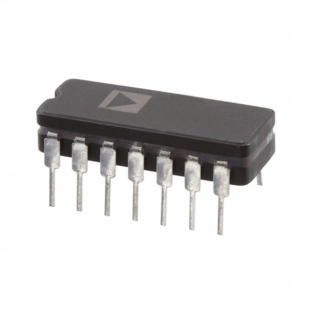
The OPA404AG is a general-purpose operational amplifier manufactured by Texas Instruments, featuring four independent amplifier circuits in a 14-CDIP through-hole package. This device is classified as a Difet® series amplifier with a product status of "Not For New Designs," indicating it is a legacy component. The OPA404AG remains in inventory with 2260 pieces available as new original stock.
Due to its discontinued design status, identifying functionally equivalent substitute parts is essential for system redesign, production continuity, and long-term component availability planning. Substitute parts must maintain electrical compatibility across critical parameters including supply voltage range, output current capability, input bias current, and thermal operating range.
Substiute Parts
Key Parameters
| Parameter | Value | Unit |
|---|---|---|
| Amplifier Type | General Purpose | — |
| Number of Circuits | 4 | Channels |
| Slew Rate | 35 | V/µs |
| Gain Bandwidth Product | 6.4 | MHz |
| Current - Input Bias | 1 | pA |
| Voltage - Input Offset | 260 | µV |
| Current - Supply (x4 Channels) | 9 | mA |
| Current - Output / Channel | 10 | mA |
| Voltage - Supply Span (Min) | 10 | V |
| Voltage - Supply Span (Max) | 36 | V |
| Operating Temperature Range | -25 to 85 | °C |
| Mounting Type | Through Hole | — |
| Package / Case | 14-CDIP (0.300", 7.62mm) | — |
| RoHS Status | ROHS3 Compliant | — |
Substitute Part Grouping Explanation
Substitution compatibility for the OPA404AG is determined by the following critical parameters:
Electrical Compatibility Criteria:
- Number of circuits: Must equal 4 independent amplifier channels
- Supply voltage range: Substitute must operate within or encompass the 10 V to 36 V span
- Output current per channel: Substitute must meet or exceed 10 mA minimum
- Input bias current: Lower values indicate superior performance; substitutes with higher bias current remain acceptable if within application tolerance
- Voltage input offset: Substitutes with comparable or lower offset voltage are acceptable
- Slew rate and bandwidth: Performance parameters that may differ; lower values indicate reduced performance capability
Mechanical Compatibility Criteria:
- Mounting type: Through-hole only
- Package footprint: 14-pin DIP configuration with 0.300" (7.62mm) spacing
Regulatory Compliance:
- RoHS3 compliance required
- REACH unaffected status required
The AD713AQ from Analog Devices Inc. meets all substitution criteria as a four-circuit amplifier in a compatible 14-pin DIP package with overlapping supply voltage range and through-hole mounting.
Parameter Comparison
| Parameter | OPA404AG (Main Part) | AD713AQ (Substitute) | Unit |
|---|---|---|---|
| Manufacturer | Texas Instruments | Analog Devices Inc. | — |
| Product Status | Not For New Designs | Active | — |
| Amplifier Type | General Purpose (Difet®) | J-FET | — |
| Number of Circuits | 4 | 4 | Channels |
| Slew Rate | 35 | 20 | V/µs |
| Gain Bandwidth Product / -3dB Bandwidth | 6.4 | 4 | MHz |
| Current - Input Bias | 1 | 10 | pA |
| Voltage - Input Offset | 260 | 300 | µV |
| Current - Supply | 9 (x4 Channels) | 10 | mA |
| Current - Output / Channel | 10 | 25 | mA |
| Voltage - Supply Span (Min) | 10 | 9 | V |
| Voltage - Supply Span (Max) | 36 | 36 | V |
| Operating Temperature Range | -25 to 85 | -40 to 85 | °C |
| Mounting Type | Through Hole | Through Hole | — |
| Package / Case | 14-CDIP (0.300", 7.62mm) | 14-CDIP (0.300", 7.62mm) | — |
| RoHS Status | ROHS3 Compliant | ROHS3 Compliant | — |
| REACH Status | REACH Unaffected | REACH Unaffected | — |
Engineering Selection Recommendations
Primary Consideration: Product Status
The OPA404AG carries a "Not For New Designs" designation, indicating Texas Instruments has discontinued active development and support for this component. The AD713AQ maintains "Active" product status from Analog Devices Inc., ensuring ongoing availability, technical support, and compliance with current regulatory standards.
Electrical Performance Trade-offs
The AD713AQ exhibits lower slew rate (20 V/µs versus 35 V/µs) and reduced bandwidth (4 MHz versus 6.4 MHz). These differences reflect the J-FET input architecture of the substitute versus the Difet® design of the original part. Applications requiring high-speed transient response or wide-bandwidth signal processing may experience performance degradation with the AD713AQ.
Conversely, the AD713AQ provides superior output current capability (25 mA per channel versus 10 mA), enabling higher load-driving capacity in output stages.
Supply Voltage Compatibility
Both devices operate across a 36 V maximum supply span. The AD713AQ extends the minimum supply voltage to 9 V (versus 10 V for OPA404AG), providing marginally improved low-voltage operation capability.
Temperature Operating Range
The AD713AQ supports an extended lower temperature limit of -40°C compared to -25°C for the OPA404AG, suitable for industrial and military-grade applications requiring broader thermal performance.
Regulatory Compliance
Both components maintain ROHS3 compliance and REACH unaffected status, satisfying current environmental and hazardous substance regulations for electronic component procurement.
Frequently Asked Questions (FAQ)
Q: Can the AD713AQ directly replace the OPA404AG in existing PCB designs?
A: Physical and electrical compatibility exists for direct pin-for-pin substitution in 14-CDIP through-hole applications. However, circuit performance may differ due to reduced slew rate and bandwidth. Functional validation is required for applications sensitive to these parameters.
Q: What are the key electrical differences between these two amplifiers?
A: The OPA404AG (Difet® general-purpose design) provides 35 V/µs slew rate and 6.4 MHz bandwidth. The AD713AQ (J-FET design) delivers 20 V/µs slew rate and 4 MHz bandwidth but offers higher output current (25 mA versus 10 mA per channel). Input bias current differs by one order of magnitude (1 pA versus 10 pA).
Q: Is the AD713AQ suitable for low-bias-current applications?
A: The AD713AQ exhibits 10 pA input bias current, which is acceptable for most general-purpose amplifier applications. However, applications requiring ultra-low input bias current below 5 pA may require alternative component selection.
Q: What is the minimum supply voltage for each device?
A: The OPA404AG requires minimum 10 V supply. The AD713AQ operates at minimum 9 V, providing 1 V additional margin for low-voltage system designs.
Q: Are both devices suitable for new product designs?
A: The OPA404AG is designated "Not For New Designs" and should not be selected for new development. The AD713AQ maintains "Active" status and is appropriate for new designs requiring four-channel general-purpose amplification in a 14-CDIP package.
Q: Do both devices meet current environmental compliance standards?
A: Yes. Both the OPA404AG and AD713AQ are ROHS3 compliant and REACH unaffected, meeting current environmental regulations for electronic component procurement and use.
Alternative Parts

SJ6012L2TP
Littelfuse Inc.
6 Alternative Parts

JMK107BBJ476MA-RE
Taiyo Yuden
10 Alternative Parts

GMK107BBJ475MA-T
Taiyo Yuden
5 Alternative Parts
SJ6020N2ARP
Littelfuse Inc.
3 Alternative Parts
SJ6025R2ATP
Littelfuse Inc.
4 Alternative Parts

2474-05L
API Delevan Inc.
1 Alternative Parts

4590R-684K
API Delevan Inc.
1 Alternative Parts

CM6560R-334
API Delevan Inc.
1 Alternative Parts

CM6460-104
API Delevan Inc.
1 Alternative Parts

5526-12
API Delevan Inc.
1 Alternative Parts