


Request Quote
(Ships tomorrow)
OP42GSZ-RL Equivalent & Substitute Parts
Part Overview
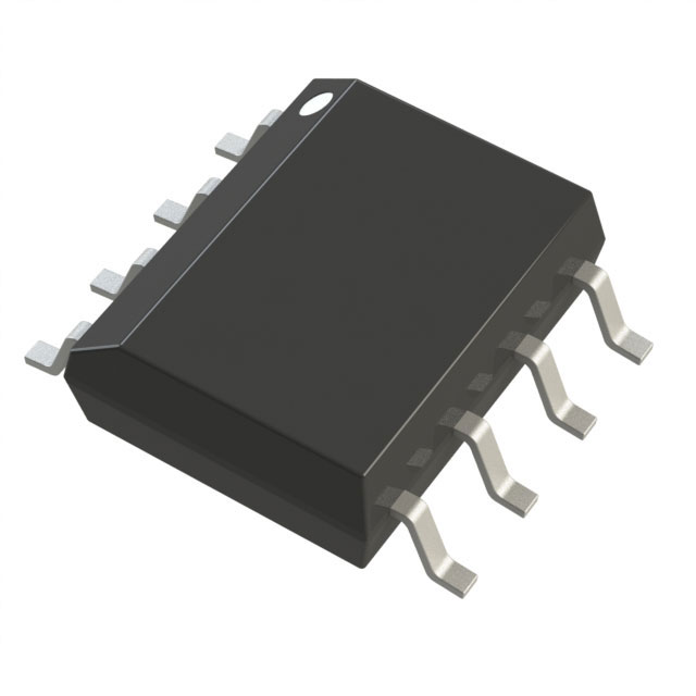
The OP42GSZ-RL is a J-FET input operational amplifier manufactured by Analog Devices Inc., housed in an 8-SOIC surface mount package. This single-circuit amplifier is designed for applications requiring low input bias current and high input impedance characteristics inherent to J-FET technology. The device is currently in active production status with 3003 units in stock.
Substitute parts are necessary when the OP42GSZ-RL becomes unavailable, when alternative packaging formats are required, or when design specifications permit operation with different amplifier topologies that maintain functional compatibility within the application's electrical constraints.
Substiute Parts
Key Parameters
| Parameter | Value | Unit |
|---|---|---|
| Amplifier Type | J-FET | — |
| Number of Circuits | 1 | — |
| Slew Rate | 50 | V/µs |
| Gain Bandwidth Product | 10 | MHz |
| Current - Input Bias | 130 | pA |
| Voltage - Input Offset | 1.5 | mV |
| Current - Supply | 5.1 | mA |
| Current - Output / Channel | 33 | mA |
| Voltage - Supply Span (Min) | 16 | V |
| Voltage - Supply Span (Max) | 40 | V |
| Operating Temperature Range | -40 to 85 | °C |
| Package / Case | 8-SOIC (0.154", 3.90mm Width) | — |
| Mounting Type | Surface Mount | — |
| RoHS Status | ROHS3 Compliant | — |
Substitute Part Grouping Explanation
Substitution of the OP42GSZ-RL is determined by compatibility across the following critical parameters:
Package Compatibility: All substitute parts must use the 8-SOIC surface mount package format (0.154", 3.90mm width) to ensure direct PCB footprint compatibility.
Circuit Count: Single-circuit configuration is mandatory; multi-circuit amplifiers are not substitutes.
Amplifier Topology: J-FET input amplifiers provide the lowest input bias current specifications and are preferred substitutes. General Purpose amplifiers with sufficiently low input bias current (≤500 nA) are acceptable substitutes when J-FET devices are unavailable.
Electrical Performance Envelope: Substitute parts must operate within the supply voltage range of 16V to 40V minimum. Slew rate, gain bandwidth product, and output current specifications must meet or exceed application requirements.
Temperature Range: Operating temperature range of -40°C to 85°C is required for direct substitution in industrial and extended-temperature applications.
Compliance & Status: Active production status is preferred. Last Time Buy and Obsolete status parts are functional substitutes but indicate limited future availability.
Parameter Comparison
| Part Number | Manufacturer | Amplifier Type | Slew Rate (V/µs) | GBW (MHz) | Input Bias (pA) | Input Offset (mV) | Supply Current (mA) | Output Current (mA) | Supply Min (V) | Supply Max (V) | Temp Range (°C) | Status |
|---|---|---|---|---|---|---|---|---|---|---|---|---|
| OP42GSZ-RL | Analog Devices | J-FET | 50 | 10 | 130 | 1.5 | 5.1 | 33 | 16 | 40 | -40 to 85 | Active |
| OPA137UA | Texas Instruments | J-FET | 3.5 | 1 | 5 | 2.5 | 0.22 | 60 | 4.5 | 36 | -40 to 85 | Active |
| OPA604AU | Texas Instruments | General Purpose | 25 | 20 | 5 | 1 | 5.3 | 35 | 9 | 48 | -25 to 85 | Active |
| OPA604AU/2K5 | Texas Instruments | General Purpose | 25 | 20 | 5 | 1 | 5.3 | 35 | 9 | 48 | -25 to 85 | Active |
| SA5534ADR | Texas Instruments | General Purpose | 13 | 10 | 500 | 0.5 | 4 | 38 | 10 | 30 | -40 to 85 | Last Time Buy |
| SA5534D | Texas Instruments | General Purpose | 13 | 10 | 500 | 0.5 | 4 | 38 | 10 | 30 | -40 to 85 | Last Time Buy |
| SA5534PSR | Texas Instruments | General Purpose | 13 | 10 | 500 | 0.5 | 4 | 38 | 10 | 30 | -40 to 85 | Last Time Buy |
| NE5534AD | onsemi | General Purpose | 13 | 10 | 500 | 0.5 | 4 | 38 | 6 | 40 | 0 to 70 | Obsolete |
| NE5534D | onsemi | General Purpose | 13 | 10 | 500 | 0.5 | 4 | 38 | 6 | 40 | 0 to 70 | Obsolete |
| SA5534AD | onsemi | General Purpose | 13 | 10 | 500 | 0.5 | 4 | 38 | 6 | 40 | -40 to 85 | Obsolete |
| HA9P5127-5ZX96 | Renesas Electronics | General Purpose | 10 | 8.5 | 15000 | 0.03 | 3.5 | 25 | 10 | 30 | 0 to 75 | Active |
Engineering Selection Recommendations
Primary Substitute - J-FET Topology (Preferred):
The OPA137UA from Texas Instruments is the recommended J-FET substitute. Both devices share J-FET input architecture, ensuring equivalent input impedance and bias current characteristics. The OPA137UA maintains active production status and ROHS3 compliance. While the OPA137UA exhibits lower slew rate (3.5 V/µs versus 50 V/µs) and reduced gain bandwidth product (1 MHz versus 10 MHz), it operates across the required temperature range (-40°C to 85°C) and accepts the OP42GSZ-RL supply voltage envelope (4.5V to 36V encompasses the 16V to 40V requirement). Selection of OPA137UA is appropriate for applications where the lower performance specifications are acceptable.
Secondary Substitutes - General Purpose Topology:
The SA5534ADR, SA5534D, and SA5534PSR (all Texas Instruments) provide general purpose amplifier operation with 10 MHz gain bandwidth product matching the OP42GSZ-RL. These devices maintain the -40°C to 85°C operating range and ROHS3 compliance. The SA5534 series exhibits higher input bias current (500 nA versus 130 pA) and reduced slew rate (13 V/µs versus 50 V/µs). Supply voltage range for SA5534 variants is 10V to 30V, which is narrower than the OP42GSZ-RL specification. These parts are designated Last Time Buy, indicating limited future availability.
The OPA604AU and OPA604AU/2K5 (Texas Instruments) offer superior performance with 20 MHz gain bandwidth product and 25 V/µs slew rate. Both maintain active production status and ROHS3 compliance. Supply voltage range extends to 48V maximum, exceeding OP42GSZ-RL specifications. Input bias current is 5 pA, substantially lower than the OP42GSZ-RL. Operating temperature range is -25°C to 85°C, which does not extend to -40°C. Selection is appropriate for applications not requiring extended low-temperature operation.
Obsolete Alternatives:
The NE5534AD and NE5534D (onsemi) are functionally equivalent to the SA5534 series but carry Obsolete status. The HA9P5127-5ZX96 (Renesas Electronics) is an active general purpose amplifier with 8.5 MHz gain bandwidth product. This device exhibits significantly higher input bias current (15 nA) and operates across 0°C to 75°C, which does not meet the -40°C lower temperature requirement.
Compliance Considerations:
All recommended substitutes maintain ROHS3 compliance and REACH Unaffected status, matching the OP42GSZ-RL regulatory posture. Moisture sensitivity levels vary; the OPA137UA and OPA604 variants specify MSL 3 (168 Hours), while the OP42GSZ-RL specifies MSL 1 (Unlimited). This difference requires attention to storage and handling procedures during component procurement and assembly.
Frequently Asked Questions (FAQ)
Q: Can the OPA137UA directly replace the OP42GSZ-RL in all applications?
A: The OPA137UA shares J-FET input topology and operates across the required temperature range. However, the OPA137UA exhibits significantly lower slew rate (3.5 V/µs versus 50 V/µs) and reduced gain bandwidth product (1 MHz versus 10 MHz). Direct substitution is appropriate only for applications where these reduced performance specifications are acceptable. Circuit simulation or bench testing is necessary to confirm functional equivalence in specific designs.
Q: What is the primary difference between J-FET and General Purpose amplifier substitutes?
A: J-FET input amplifiers (OP42GSZ-RL, OPA137UA) provide extremely low input bias current (130 pA and 5 pA respectively), making them suitable for high-impedance signal sources and precision measurement applications. General Purpose amplifiers (SA5534 series, OPA604 series) typically exhibit higher input bias current (500 nA to 5 pA) but often provide superior slew rate and gain bandwidth product. Selection depends on whether the application prioritizes input impedance characteristics or dynamic performance.
Q: Why do some substitute parts have narrower supply voltage ranges?
A: The SA5534 series specifies 10V to 30V supply range, which is narrower than the OP42GSZ-RL specification of 16V to 40V. This reflects design differences in the internal voltage regulation and biasing networks. Applications requiring operation at supply voltages below 10V or above 30V cannot use SA5534 variants. The OPA604 series extends to 48V maximum, providing greater flexibility for high-voltage applications.
Q: What does "Last Time Buy" status mean for substitute parts?
A: Last Time Buy status indicates that the manufacturer has announced end-of-life for the device. Existing inventory is available for purchase, but no new production will occur after a specified date. Parts with this designation (SA5534ADR, SA5534D, SA5534PSR) remain functionally equivalent but should not be selected for new designs requiring long-term component availability. These parts are appropriate for sustaining production of existing products with known end-of-life dates.
Q: Are there package format differences among the substitute parts?
A: The OP42GSZ-RL is packaged in 8-SOIC (0.154", 3.90mm width) in Tape & Reel format. Most substitutes use identical 8-SOIC packaging. The SA5534PSR uses 8-SO package (0.209", 5.30mm width), which has a different footprint and is not a direct PCB substitute despite electrical equivalence. Verify package dimensions before selecting SA5534PSR as a replacement.
Q: How do input offset voltage specifications affect substitution decisions?
A: The OP42GSZ-RL specifies 1.5 mV input offset voltage. Substitute parts range from 0.03 mV (HA9P5127-5ZX96) to 2.5 mV (OPA137UA). For applications with precision DC coupling or low-level signal amplification, input offset voltage drift with temperature becomes significant. The OPA604AU specifies 1 mV, providing closer matching to the OP42GSZ-RL. General Purpose amplifiers in the SA5534 series specify 0.5 mV, which is superior. Selection should account for the application's offset voltage budget and temperature stability requirements.
Q: What is the significance of Moisture Sensitivity Level (MSL) differences?
A: The OP42GSZ-RL specifies MSL 1 (Unlimited), meaning the component has no moisture sensitivity restrictions. The OPA137UA and OPA604 variants specify MSL 3 (168 Hours), requiring that the component be used within 168 hours of package opening if stored in non-controlled humidity environments. This affects procurement logistics and assembly scheduling. Components with higher MSL ratings require dry-pack storage and bake-out procedures before reflow soldering.
Q: Can the OPA604AU be used in applications requiring -40°C operation?
A: The OPA604AU specifies operating temperature range of -25°C to 85°C, which does not extend to -40°C. Applications requiring guaranteed operation at -40°C must use the OP42GSZ-RL, OPA137UA, SA5534 variants, or SA5534AD. The OPA604AU is not suitable for extended low-temperature applications.
Q: How should I evaluate whether a substitute part is acceptable for my application?
A: Substitution evaluation requires comparison of the application's electrical requirements against the substitute part's specifications. Critical parameters include: (1) supply voltage range compatibility, (2) operating temperature range coverage, (3) input bias current and offset voltage requirements, (4) slew rate and gain bandwidth product adequacy, (5) output current capability, and (6) package footprint compatibility. Electrical simulation using the substitute part's SPICE model is recommended to verify circuit performance before hardware implementation.
Alternative Parts

SJ6012L2TP
Littelfuse Inc.
6 Alternative Parts

JMK107BBJ476MA-RE
Taiyo Yuden
10 Alternative Parts

GMK107BBJ475MA-T
Taiyo Yuden
5 Alternative Parts
SJ6020N2ARP
Littelfuse Inc.
3 Alternative Parts
SJ6025R2ATP
Littelfuse Inc.
4 Alternative Parts

2474-05L
API Delevan Inc.
1 Alternative Parts

4590R-684K
API Delevan Inc.
1 Alternative Parts

CM6560R-334
API Delevan Inc.
1 Alternative Parts

CM6460-104
API Delevan Inc.
1 Alternative Parts

5526-12
API Delevan Inc.
1 Alternative Parts