


Request Quote
(Ships tomorrow)
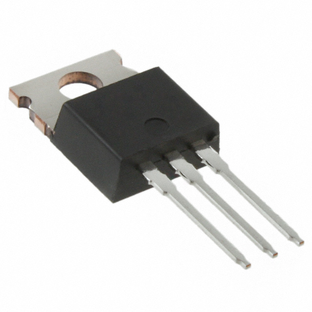
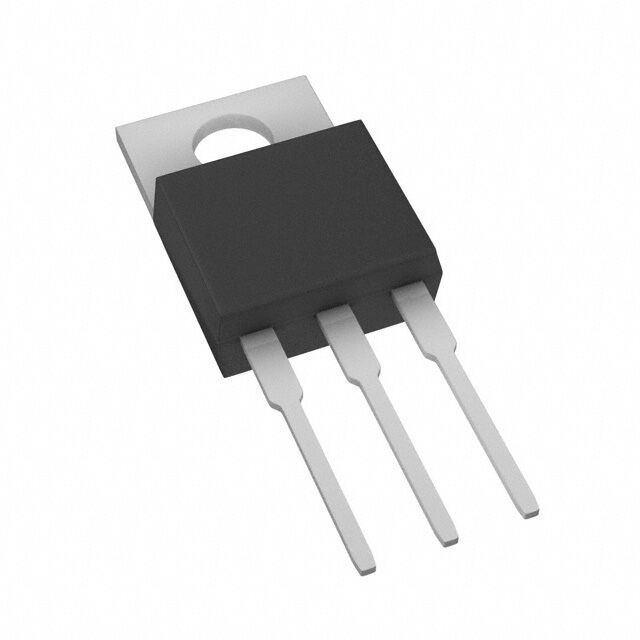
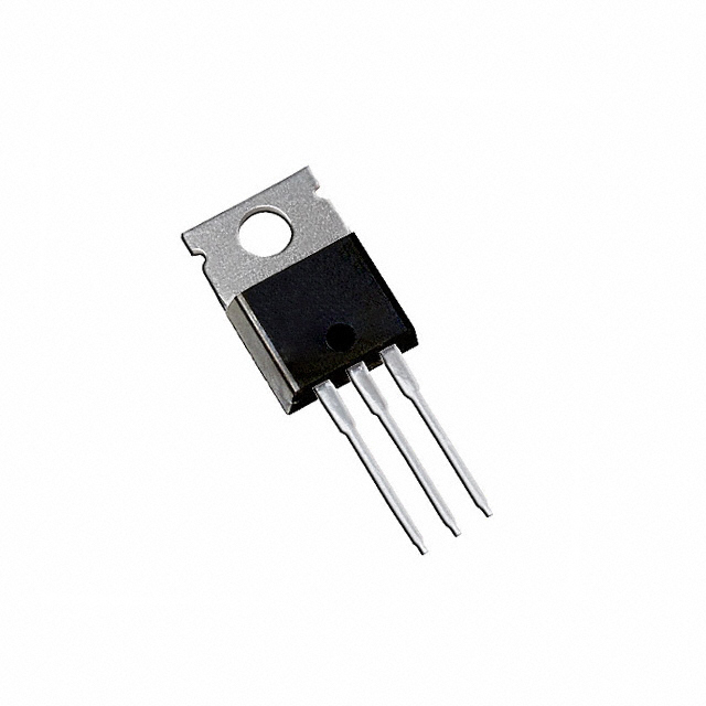
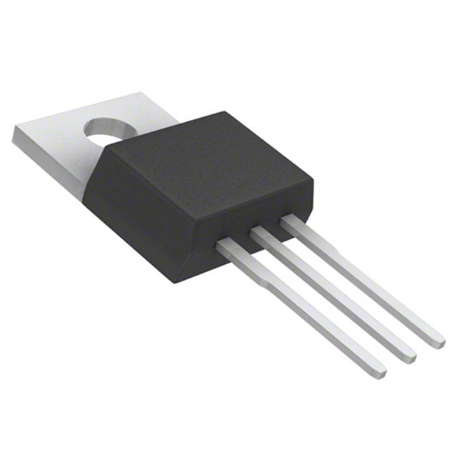
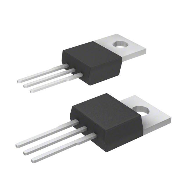
NTP18N06 N-Channel MOSFET 60V 15A TO-220 Equivalent & Substitute Parts
Part Overview
The NTP18N06 is an N-Channel MOSFET manufactured by onsemi, rated for 60V drain-to-source voltage and 15A continuous drain current in a TO-220 through-hole package. This device is classified as obsolete, making identification of equivalent and substitute parts essential for ongoing design support and production continuity. The part operates across a temperature range of -55°C to 175°C and dissipates up to 48.4W at the case temperature. Substitution is necessary to ensure component availability and maintain design functionality in applications requiring N-Channel MOSFET performance within the specified voltage and current parameters.
Substiute Parts
Key Parameters
| Parameter | Value | Unit |
|---|---|---|
| Drain-to-Source Voltage (Vdss) | 60 | V |
| Continuous Drain Current (Id) @ 25°C | 15 | A |
| On-State Resistance (Rds On) @ 7.5A, 10V | 90 | mOhm |
| Gate Threshold Voltage (Vgs(th)) @ 250µA | 4 | V |
| Gate Charge (Qg) @ 10V | 22 | nC |
| Input Capacitance (Ciss) @ 25V | 450 | pF |
| Power Dissipation (Max) | 48.4 | W |
| Operating Temperature Range | -55 to 175 | °C |
| Package Type | TO-220-3 | Through Hole |
| FET Type | N-Channel | — |
| Technology | MOSFET (Metal Oxide) | — |
Substitute Part Grouping Explanation
Substitution of the NTP18N06 is determined by strict adherence to the following electrical and mechanical parameters:
Primary Substitution Criteria:
- Drain-to-Source Voltage (Vdss): Must equal or exceed 60V
- Continuous Drain Current (Id): Must equal or exceed 15A at 25°C
- Package Type: Must be TO-220-3 through-hole configuration
- FET Type: Must be N-Channel
- Technology: Must be MOSFET (Metal Oxide)
- Gate Drive Voltage: Must support 10V operation
- Operating Temperature Range: Must encompass -55°C to 175°C or be compatible with application requirements
Secondary Compatibility Parameters:
- On-State Resistance (Rds On): Lower values indicate improved performance but do not disqualify substitution
- Gate Charge (Qg): Affects switching speed; higher values acceptable if application timing permits
- Input Capacitance (Ciss): Influences gate drive requirements; variations acceptable within circuit design margins
- Power Dissipation: Higher ratings provide design margin; lower ratings require thermal verification
The substitute parts listed below meet or exceed the primary criteria, ensuring functional compatibility with the NTP18N06 in applications requiring N-Channel MOSFET performance at 60V and 15A or greater ratings.
Parameter Comparison
| Parameter | NTP18N06 | IPP015N04NGXKSA1 | IPP50R199CPXKSA1 | IPP60R125CPXKSA1 | IPP60R165CPXKSA1 | IPP60R199CPXKSA1 | IPP60R299CPXKSA1 | IPP80N03S4L03AKSA1 | IPP80N08S2L07AKSA1 | IRF1010EPBF | IRF1010EZPBF |
|---|---|---|---|---|---|---|---|---|---|---|---|
| Manufacturer | onsemi | Infineon | Infineon | Infineon | Infineon | Infineon | Infineon | Infineon | Infineon | Infineon | Infineon |
| Vdss (V) | 60 | 40 | 550 | 650 | 600 | 650 | 650 | 30 | 75 | 60 | 60 |
| Id @ 25°C (A) | 15 | 120 | 17 | 25 | 21 | 16 | 11 | 80 | 80 | 84 | 75 |
| Rds On (mOhm) | 90 @ 7.5A, 10V | 1.5 @ 100A, 10V | 199 @ 9.9A, 10V | 125 @ 16A, 10V | 165 @ 12A, 10V | 199 @ 9.9A, 10V | 299 @ 6.6A, 10V | 2.7 @ 80A, 10V | 7.1 @ 80A, 10V | 12 @ 50A, 10V | 8.5 @ 51A, 10V |
| Vgs(th) (V) | 4 @ 250µA | 4 @ 200µA | 3.5 @ 660µA | 3.5 @ 1.1mA | 3.5 @ 790µA | 3.5 @ 660µA | 3.5 @ 440µA | 2.2 @ 90µA | 2 @ 250µA | 4 @ 250µA | 4 @ 100µA |
| Qg @ 10V (nC) | 22 | 250 | 45 | 70 | 52 | 43 | 29 | 140 | 233 | 130 | 86 |
| Ciss @ Vds (pF) | 450 @ 25V | 20000 @ 20V | 1800 @ 100V | 2500 @ 100V | 2000 @ 100V | 1520 @ 100V | 1100 @ 100V | 9750 @ 25V | 5400 @ 25V | 3210 @ 25V | 2810 @ 25V |
| Power Dissipation (W) | 48.4 | 250 | 139 | 208 | 192 | 139 | 96 | 136 | 300 | 200 | 140 |
| Operating Temp Range (°C) | -55 to 175 | -55 to 175 | -55 to 150 | -55 to 150 | -55 to 150 | -55 to 150 | -55 to 150 | -55 to 175 | -55 to 175 | -55 to 175 | -55 to 175 |
| Package | TO-220-3 | TO-220-3 | TO-220-3 | TO-220-3 | TO-220-3 | TO-220-3 | TO-220-3 | TO-220-3 | TO-220-3 | TO-220-3 | TO-220-3 |
| Product Status | Obsolete | Active | Not For New Designs | Not For New Designs | Not For New Designs | Not For New Designs | Not For New Designs | Active | Obsolete | Not For New Designs | Active |
| RoHS Status | Non-compliant | ROHS3 Compliant | ROHS3 Compliant | ROHS3 Compliant | ROHS3 Compliant | ROHS3 Compliant | ROHS3 Compliant | ROHS3 Compliant | ROHS3 Compliant | ROHS3 Compliant | ROHS3 Compliant |
Engineering Selection Recommendations
Direct Voltage and Current Match (60V, ≥15A):
The IRF1010EZPBF and IRF1010EPBF are the closest functional equivalents to the NTP18N06, both rated at 60V drain-to-source voltage with drain currents of 75A and 84A respectively. The IRF1010EZPBF is the preferred choice due to its Active product status, ensuring long-term availability and manufacturing support. Both devices operate across the full -55°C to 175°C temperature range and are housed in TO-220-3 packages. The IRF1010EZPBF exhibits superior on-state resistance (8.5mOhm) compared to the NTP18N06 (90mOhm), providing improved thermal performance and reduced power dissipation in switching applications.
Higher Voltage Rated Alternatives (≥60V, ≥15A):
The IPP80N08S2L07AKSA1 (75V, 80A) and IPP80N03S4L03AKSA1 (30V, 80A) provide higher current ratings and enhanced thermal dissipation capabilities. The IPP80N08S2L07AKSA1 operates at 75V, exceeding the NTP18N06 voltage specification, and is suitable for applications requiring additional voltage margin. The IPP80N03S4L03AKSA1, while rated at only 30V, offers significantly higher current capacity (80A) and is Active in product status, making it suitable for lower-voltage applications where the NTP18N06 would be over-specified.
Compliance and Availability Considerations:
All substitute parts listed are ROHS3 compliant, addressing environmental and regulatory requirements that the obsolete NTP18N06 does not meet. The IPP015N04NGXKSA1 and IRF1010EZPBF carry Active product status, ensuring continued manufacturing and supply chain support. Parts designated as "Not For New Designs" remain functionally equivalent but may face future availability constraints.
Application-Specific Selection:
For applications requiring exact voltage matching at 60V with improved performance characteristics, the IRF1010EZPBF is the recommended primary substitute. For applications where higher voltage ratings provide design margin, the IPP80N08S2L07AKSA1 is suitable. For cost-sensitive applications or those requiring maximum current capacity at lower voltages, the IPP80N03S4L03AKSA1 or IPP015N04NGXKSA1 provide alternatives with Active status.
Frequently Asked Questions (FAQ)
Q: Can the IRF1010EZPBF directly replace the NTP18N06 without circuit modifications?
A: The IRF1010EZPBF is functionally compatible with the NTP18N06 in TO-220-3 package applications. Both devices operate at 60V, support 10V gate drive, and span the -55°C to 175°C temperature range. The IRF1010EZPBF provides superior on-state resistance (8.5mOhm vs. 90mOhm), resulting in lower power dissipation. Gate charge and input capacitance differ, requiring verification that gate drive circuitry can accommodate the IRF1010EZPBF's 86nC gate charge specification. No circuit modifications are typically required for basic switching applications.
Q: What is the significance of the voltage rating difference between the NTP18N06 (60V) and higher-rated alternatives like the IPP60R199CPXKSA1 (650V)?
A: Drain-to-source voltage rating indicates the maximum voltage the device can block in the off-state. The NTP18N06 is rated for 60V maximum. Higher-rated devices such as the IPP60R199CPXKSA1 (650V) can operate safely in applications with higher voltage requirements but are not required for 60V applications. Using a higher-voltage-rated device in a 60V circuit introduces no functional penalty; however, on-state resistance typically increases with voltage rating, potentially affecting efficiency. Device selection should match application voltage requirements without unnecessary over-specification.
Q: Why do some substitute parts have lower continuous drain current ratings than the NTP18N06?
A: The NTP18N06 is rated for 15A continuous drain current at 25°C case temperature. Substitute parts with lower current ratings, such as the IPP60R199CPXKSA1 (16A) and IPP60R299CPXKSA1 (11A), are not suitable for applications requiring the full 15A specification. These parts are listed as alternatives only for applications where actual current requirements are lower than the NTP18N06 rating. Substitution must ensure the selected device's continuous drain current rating meets or exceeds the application's maximum sustained current requirement.
Q: What does "Not For New Designs" product status mean for substitution purposes?
A: "Not For New Designs" indicates that the manufacturer has discontinued active development and marketing of the part, though existing inventory may remain available. These parts remain functionally equivalent and suitable for replacement in existing designs or production continuity. However, for new product development, parts with Active status such as the IRF1010EZPBF or IPP015N04NGXKSA1 are preferred to ensure long-term supply chain stability and manufacturing support.
Q: How does on-state resistance (Rds On) affect device selection?
A: On-state resistance determines power dissipation when the MOSFET conducts current. The NTP18N06 exhibits 90mOhm at 7.5A and 10V gate drive. Lower Rds On values reduce power loss and heat generation. The IRF1010EZPBF (8.5mOhm) dissipates significantly less power than the NTP18N06 in the same application. However, Rds On specifications are measured at different current levels across devices, requiring normalized comparison. Lower Rds On is advantageous for thermal performance but does not disqualify higher-resistance alternatives if thermal design accommodates the increased dissipation.
Q: Are all listed substitute parts available in the same TO-220-3 package configuration?
A: All substitute parts listed are housed in TO-220-3 through-hole packages, ensuring mechanical and thermal interface compatibility with the NTP18N06. Package designation variations such as "TO-220AB" and "PG-TO220-3-1" refer to manufacturer-specific package nomenclature but represent the same physical TO-220-3 form factor. Pin configuration and lead spacing are identical across all listed devices, permitting direct socket substitution without PCB modification.
Q: What is the importance of gate charge (Qg) in MOSFET substitution?
A: Gate charge represents the total charge required to drive the MOSFET from off to on state at a specified gate voltage. The NTP18N06 requires 22nC at 10V. Substitute parts exhibit varying gate charge specifications; for example, the IRF1010EZPBF requires 86nC. Higher gate charge demands greater current from the gate drive circuit and extends switching time. Substitution is acceptable if the gate drive circuit can supply the required charge within the application's timing constraints. Gate drive circuit verification is necessary when gate charge differs significantly from the original device.
Q: Can the NTP18N06 be substituted with lower-voltage-rated devices such as the IPP80N03S4L03AKSA1 (30V)?
A: No. The IPP80N03S4L03AKSA1 is rated for 30V maximum drain-to-source voltage, which is insufficient for applications designed for the NTP18N06's 60V rating. Using a lower-voltage-rated device in a 60V circuit risks device failure and circuit damage. Substitution must maintain or exceed the original device's voltage specification. The IPP80N03S4L03AKSA1 is suitable only for applications where the actual operating voltage does not exceed 30V.
Q: What compliance advantages do the substitute parts offer compared to the NTP18N06?
A: The NTP18N06 is RoHS non-compliant, indicating it contains restricted substances such as lead. All listed substitute parts are ROHS3 compliant, meeting current environmental and regulatory requirements for electronic components in many jurisdictions. ROHS3 compliance is mandatory for new product designs and increasingly required for replacement components in existing products. Substitution with ROHS3-compliant alternatives ensures regulatory compliance and supports long-term product certification requirements.
Alternative Parts

SJ6012L2TP
Littelfuse Inc.
6 Alternative Parts

JMK107BBJ476MA-RE
Taiyo Yuden
10 Alternative Parts

GMK107BBJ475MA-T
Taiyo Yuden
5 Alternative Parts
SJ6020N2ARP
Littelfuse Inc.
3 Alternative Parts
SJ6025R2ATP
Littelfuse Inc.
4 Alternative Parts

2474-05L
API Delevan Inc.
1 Alternative Parts

4590R-684K
API Delevan Inc.
1 Alternative Parts

CM6560R-334
API Delevan Inc.
1 Alternative Parts

CM6460-104
API Delevan Inc.
1 Alternative Parts

5526-12
API Delevan Inc.
1 Alternative Parts