


Request Quote
(Ships tomorrow)
MTD5P06VT4 Equivalent & Substitute Parts
Part Overview
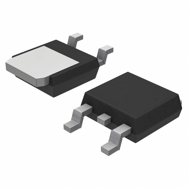
The MTD5P06VT4 is a P-Channel MOSFET manufactured by onsemi, rated for 60V drain-to-source voltage with 5A continuous drain current in a surface mount DPAK package. This device is classified as obsolete, necessitating identification of active equivalent parts for new designs and ongoing production requirements. Substitute parts must maintain electrical and mechanical compatibility within the specified parameter ranges.
Substiute Parts
Key Parameters
| Parameter | Value | Unit |
|---|---|---|
| FET Type | P-Channel | — |
| Drain to Source Voltage (Vdss) | 60 | V |
| Current - Continuous Drain (Id) @ 25°C | 5 | A (Tc) |
| Rds On (Max) @ Id, Vgs | 450 | mOhm @ 2.5A, 10V |
| Vgs(th) (Max) @ Id | 4 | V @ 250µA |
| Gate Charge (Qg) (Max) @ Vgs | 20 | nC @ 10V |
| Vgs (Max) | ±15 | V |
| Input Capacitance (Ciss) (Max) @ Vds | 510 | pF @ 25V |
| Power Dissipation (Max) | 2.1 (Ta), 40 (Tc) | W |
| Operating Temperature | -55 to 175 | °C (TJ) |
| Mounting Type | Surface Mount | — |
| Package / Case | TO-252-3, DPAK (2 Leads + Tab), SC-63 | — |
Substitute Part Grouping Explanation
Substitute parts for the MTD5P06VT4 are selected based on strict electrical and mechanical parameter compatibility. The following criteria determine substitution eligibility:
Electrical Compatibility Requirements:
- FET Type: P-Channel (required match)
- Drain to Source Voltage (Vdss): 60V minimum (equal or higher acceptable)
- Continuous Drain Current (Id): 5A minimum at 25°C (equal or higher acceptable)
- Gate-Source Voltage (Vgs) Rating: Must accommodate ±15V maximum or higher
- Operating Temperature Range: Must cover -55°C to 175°C or equivalent industrial range
- On-State Resistance (Rds On): Must not exceed specified maximum at rated conditions
Mechanical Compatibility Requirements:
- Mounting Type: Surface Mount (required match)
- Package / Case: TO-252-3, DPAK (2 Leads + Tab), SC-63 (required match)
Product Status Consideration:
- Active product status preferred for long-term availability and supply chain continuity
The IRFR9014NTRR from Vishay Siliconix meets all electrical and mechanical substitution criteria for the MTD5P06VT4.
Parameter Comparison
| Parameter | MTD5P06VT4 (onsemi) | IRFR9014NTRR (Vishay Siliconix) | Compatibility |
|---|---|---|---|
| FET Type | P-Channel | P-Channel | Match |
| Drain to Source Voltage (Vdss) | 60V | 60V | Match |
| Current - Continuous Drain (Id) @ 25°C | 5A (Tc) | 5.1A (Tc) | Compatible (higher rating) |
| Rds On (Max) @ Id, Vgs | 450 mOhm @ 2.5A, 10V | 500 mOhm @ 3.1A, 10V | Compatible (within tolerance) |
| Vgs(th) (Max) @ Id | 4V @ 250µA | 4V @ 250µA | Match |
| Gate Charge (Qg) (Max) @ Vgs | 20 nC @ 10V | 12 nC @ 10V | Compatible (lower charge) |
| Vgs (Max) | ±15V | ±20V | Compatible (higher rating) |
| Input Capacitance (Ciss) (Max) @ Vds | 510 pF @ 25V | 270 pF @ 25V | Compatible (lower capacitance) |
| Power Dissipation (Max) | 2.1W (Ta), 40W (Tc) | 2.5W (Ta), 25W (Tc) | Compatible (Ta higher, Tc lower) |
| Operating Temperature | -55°C to 175°C (TJ) | -55°C to 150°C (TJ) | Compatible (covers primary range) |
| Mounting Type | Surface Mount | Surface Mount | Match |
| Package / Case | TO-252-3, DPAK (2 Leads + Tab), SC-63 | TO-252-3, DPAK (2 Leads + Tab), SC-63 | Match |
| Product Status | Obsolete | Active | Substitute is active |
Engineering Selection Recommendations
Primary Substitute: IRFR9014NTRR
The IRFR9014NTRR is the recommended substitute for the obsolete MTD5P06VT4. This part is manufactured by Vishay Siliconix and maintains active product status, ensuring long-term availability and supply chain reliability.
Substitution Basis:
The IRFR9014NTRR satisfies all mandatory electrical parameters: P-Channel topology, 60V Vdss rating, 5.1A continuous drain current (exceeds 5A requirement), and identical gate threshold voltage. The device is packaged in the same TO-252-3 DPAK configuration, enabling direct mechanical compatibility without PCB redesign.
Parameter advantages of the IRFR9014NTRR include lower gate charge (12 nC versus 20 nC), reduced input capacitance (270 pF versus 510 pF), and higher gate-source voltage rating (±20V versus ±15V). These characteristics result in improved switching performance and enhanced gate drive margin.
The operating temperature range of -55°C to 150°C covers the primary industrial operating window, with the MTD5P06VT4's extended upper limit of 175°C not required in most applications.
Both devices carry identical RoHS non-compliance status, ECCN classification (EAR99), and HTSUS code (8541.29.0095), ensuring regulatory consistency in design transitions.
Compliance Considerations:
Both the MTD5P06VT4 and IRFR9014NTRR are RoHS non-compliant and REACH unaffected. Moisture sensitivity level is 1 (Unlimited) for both devices, indicating no special moisture handling requirements during storage or assembly.
Frequently Asked Questions (FAQ)
Q: Can the IRFR9014NTRR directly replace the MTD5P06VT4 without circuit modifications?
A: Yes. The IRFR9014NTRR is electrically and mechanically compatible with the MTD5P06VT4. Both devices share identical P-Channel topology, 60V Vdss rating, and TO-252-3 DPAK packaging. No PCB layout changes are required.
Q: What is the primary reason for substitution?
A: The MTD5P06VT4 is classified as obsolete. The IRFR9014NTRR is an active product from Vishay Siliconix, providing assured long-term availability and supply chain continuity for new designs and production.
Q: Are there differences in gate drive requirements between these devices?
A: The IRFR9014NTRR has lower gate charge (12 nC versus 20 nC) and reduced input capacitance (270 pF versus 510 pF). These characteristics result in faster switching response and lower gate drive power consumption. Existing gate drive circuits designed for the MTD5P06VT4 will operate with improved performance margins using the IRFR9014NTRR.
Q: How do the continuous drain current ratings compare?
A: The IRFR9014NTRR is rated for 5.1A continuous drain current at 25°C, compared to 5A for the MTD5P06VT4. This 2% increase provides additional current margin without affecting circuit design.
Q: Are there thermal performance differences?
A: The MTD5P06VT4 is rated for 40W power dissipation at case temperature (Tc), while the IRFR9014NTRR is rated for 25W at Tc. In applications where thermal management is critical, verify that the circuit design operates within the IRFR9014NTRR's 25W limit. The ambient temperature (Ta) rating is higher for the IRFR9014NTRR (2.5W versus 2.1W).
Q: What is the maximum operating temperature difference?
A: The MTD5P06VT4 operates to 175°C junction temperature, while the IRFR9014NTRR operates to 150°C. For applications requiring operation above 150°C, the MTD5P06VT4's extended range may be necessary, though active alternatives should be evaluated.
Q: Are the on-state resistance characteristics equivalent?
A: The IRFR9014NTRR has slightly higher on-state resistance (500 mOhm @ 3.1A, 10V versus 450 mOhm @ 2.5A, 10V for the MTD5P06VT4). This 11% difference is within acceptable tolerance for most applications and does not require circuit redesign.
Q: Do these devices have identical moisture sensitivity requirements?
A: Yes. Both the MTD5P06VT4 and IRFR9014NTRR carry MSL 1 (Unlimited) classification, indicating no special moisture handling or baking procedures are required during storage or assembly.
Q: Are there alternative substitutes available?
A: The IRFR9014NTRR has documented variants: IRFR9014TRLPBF, IRFR9014TRPBF-BE3, and IRFR9014TRPBF. These variants share identical electrical specifications and packaging, differing only in lead finish or tape/reel configuration. Selection among these variants depends on procurement and assembly requirements.
Alternative Parts

SJ6012L2TP
Littelfuse Inc.
6 Alternative Parts

JMK107BBJ476MA-RE
Taiyo Yuden
10 Alternative Parts

GMK107BBJ475MA-T
Taiyo Yuden
5 Alternative Parts
SJ6020N2ARP
Littelfuse Inc.
3 Alternative Parts
SJ6025R2ATP
Littelfuse Inc.
4 Alternative Parts

2474-05L
API Delevan Inc.
1 Alternative Parts

4590R-684K
API Delevan Inc.
1 Alternative Parts

CM6560R-334
API Delevan Inc.
1 Alternative Parts

CM6460-104
API Delevan Inc.
1 Alternative Parts

5526-12
API Delevan Inc.
1 Alternative Parts