


Request Quote
(Ships tomorrow)
MPIA4040R3-1R2-R Equivalent & Substitute Parts
Part Overview
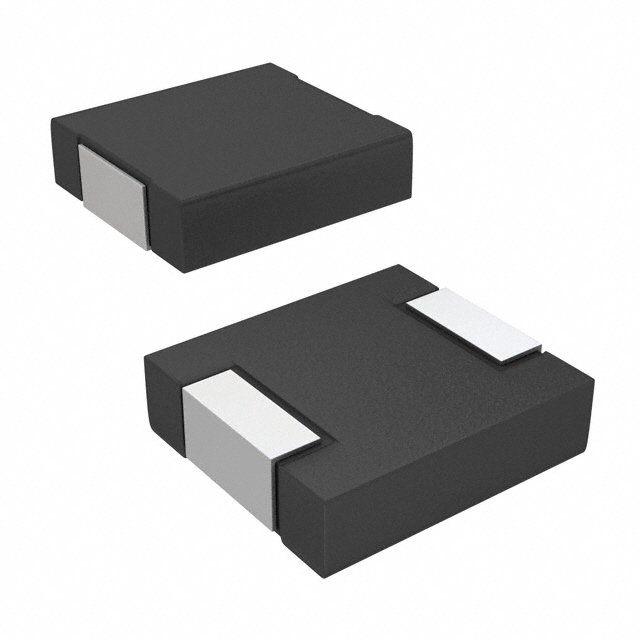
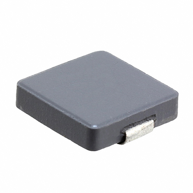
The MPIA4040R3-1R2-R is a 1.2 µH shielded molded inductor manufactured by Eaton - Electronics Division. This component is rated for 4 A continuous current with a maximum DC resistance of 32 mOhm and operates across the temperature range of -55°C to 125°C. The part is classified as obsolete, necessitating identification of equivalent substitute components for ongoing design support and procurement continuity. Substitute parts must maintain the same inductance value, shielding characteristics, and thermal operating range while accommodating variations in current rating and DC resistance within acceptable application parameters.
Substiute Parts
Key Parameters
| Parameter | Value | Unit | Criticality for Substitution |
|---|---|---|---|
| Inductance | 1.2 | µH | Critical - Must Match |
| Current Rating | 4 | A | Critical - Minimum Threshold |
| DC Resistance (DCR) | 32 | mOhm Max | Critical - Power Loss Parameter |
| Shielding | Shielded | - | Critical - EMI Containment |
| Operating Temperature | -55 to 125 | °C | Critical - Thermal Compatibility |
| Mounting Type | Surface Mount | - | Critical - PCB Assembly |
| Tolerance | ±20 | % | Standard - Electrical Performance |
| Inductance Test Frequency | 100 | kHz | Reference - Measurement Standard |
Substitute Part Grouping Explanation
Substitute parts for the MPIA4040R3-1R2-R are identified based on strict electrical and mechanical parameter alignment. The substitution logic is governed by the following criteria:
Primary Matching Criteria (Non-Negotiable):
- Inductance value: 1.2 µH (exact match required)
- Shielding type: Shielded (electromagnetic containment requirement)
- Mounting type: Surface Mount (PCB assembly compatibility)
- Operating temperature range: Minimum -55°C to 125°C coverage
- Tolerance: ±20% (standard specification)
Secondary Compatibility Criteria (Application-Dependent):
- Current rating: Substitute must equal or exceed 4 A minimum
- DC resistance: Substitute must not exceed 32 mOhm maximum (power dissipation constraint)
- Package dimensions: Physical footprint compatibility with PCB layout
Identified Substitutes:
- IHLP1616ABER1R2M11 (Vishay Dale) - Direct electrical equivalent with reduced current rating
- SRP1238A-1R2M (Bourns Inc.) - Superior current and thermal performance with different core technology
Parameter Comparison
| Parameter | MPIA4040R3-1R2-R (Eaton) | IHLP1616ABER1R2M11 (Vishay Dale) | SRP1238A-1R2M (Bourns) |
|---|---|---|---|
| Inductance | 1.2 µH | 1.2 µH | 1.2 µH |
| Tolerance | ±20% | ±20% | ±20% |
| Current Rating | 4 A | 3.75 A | 21 A |
| Current - Saturation (Isat) | 9.4 A | 3.75 A | 37 A |
| DC Resistance (DCR) | 32 mOhm Max | 58.5 mOhm Max | 4 mOhm Max |
| Shielding | Shielded | Shielded | Shielded |
| Core Material | Metal Composite | Not Specified | Carbonyl Powder |
| Type | Molded | Molded | Drum Core, Wirewound |
| Operating Temperature | -55°C to 125°C | -55°C to 125°C | -40°C to 150°C |
| Frequency - Self Resonant | Not Specified | 62 MHz | 35 MHz |
| Q @ 100 kHz | Not Specified | Not Specified | 20 |
| Size / Dimension | 4.45mm L x 4.06mm W | 4.45mm L x 4.06mm W | 13.50mm L x 12.50mm W |
| Height - Seated (Max) | 1.80 mm | 1.20 mm | 3.50 mm |
| Product Status | Obsolete | Active | Active |
| Ratings | AEC-Q200 | Not Specified | AEC-Q200 |
| RoHS Status | Not Specified | ROHS3 Compliant | ROHS3 Compliant |
Engineering Selection Recommendations
IHLP1616ABER1R2M11 (Vishay Dale) - Direct Replacement:
This substitute is recommended as the primary direct replacement for the obsolete MPIA4040R3-1R2-R. It maintains identical inductance (1.2 µH), shielding, tolerance (±20%), and operating temperature range (-55°C to 125°C). The component is currently in active production with 11,671 units in stock. Physical dimensions are identical (4.45mm L x 4.06mm W), ensuring PCB layout compatibility. The current rating of 3.75 A is marginally below the original 4 A specification; however, this substitution is valid for applications where the actual operating current does not exceed 3.75 A continuous. The increased DC resistance (58.5 mOhm vs. 32 mOhm) results in higher power dissipation and must be evaluated against thermal design margins. This part is ROHS3 compliant and REACH unaffected, meeting modern environmental standards.
SRP1238A-1R2M (Bourns Inc.) - Performance Upgrade:
This substitute is recommended for applications requiring enhanced current capacity and reduced power dissipation. The SRP1238A-1R2M maintains the 1.2 µH inductance and ±20% tolerance with significantly superior electrical performance: 21 A current rating and 4 mOhm DC resistance. The component is AEC-Q200 rated and ROHS3 compliant. Operating temperature range extends to 150°C, providing additional thermal margin. However, this substitute has a larger physical footprint (13.50mm L x 12.50mm W vs. 4.45mm L x 4.06mm W) and greater height (3.50 mm vs. 1.80 mm), requiring PCB layout verification for space constraints. The different core technology (Carbonyl Powder wirewound vs. Metal Composite molded) may affect high-frequency behavior; the self-resonant frequency of 35 MHz is lower than the IHLP1616ABER1R2M11 (62 MHz). This substitute is suitable for designs where thermal performance and current capacity are prioritized over compact form factor.
Frequently Asked Questions (FAQ)
Q1: Can IHLP1616ABER1R2M11 be used as a direct drop-in replacement for MPIA4040R3-1R2-R?
A: IHLP1616ABER1R2M11 is electrically and mechanically compatible for direct PCB substitution. Identical physical dimensions (4.45mm x 4.06mm) and surface mount packaging enable direct placement. However, the reduced current rating (3.75 A vs. 4 A) and increased DC resistance (58.5 mOhm vs. 32 mOhm) must be verified against circuit operating conditions. If the application operates at or near 4 A continuous current, thermal analysis is required to confirm acceptable power dissipation with the higher DCR value.
Q2: What is the impact of increased DC resistance in IHLP1616ABER1R2M11?
A: DC resistance directly affects power dissipation according to P = I²R. At 4 A, the MPIA4040R3-1R2-R dissipates 512 mW (4² × 0.032), while IHLP1616ABER1R2M11 dissipates 936 mW (4² × 0.0585). This 83% increase in power dissipation requires verification that PCB thermal design and component placement accommodate the additional heat generation. For applications operating below 3.75 A, power dissipation remains within acceptable limits.
Q3: When should SRP1238A-1R2M be selected over IHLP1616ABER1R2M11?
A: SRP1238A-1R2M is selected when the application requires current capacity exceeding 3.75 A or when minimizing power dissipation is critical. The 21 A rating and 4 mOhm DCR provide substantial margin for high-current applications. At 4 A, SRP1238A-1R2M dissipates only 64 mW, compared to 512 mW for the original part. The trade-off is significantly larger physical dimensions (13.50mm x 12.50mm), which may not fit compact PCB layouts. Verify available board space before selection.
Q4: Are there temperature range limitations when substituting these parts?
A: IHLP1616ABER1R2M11 matches the original operating range (-55°C to 125°C) exactly. SRP1238A-1R2M extends the upper limit to 150°C, providing additional thermal margin. Both substitutes maintain the -55°C lower limit. For applications operating near the upper temperature boundary, SRP1238A-1R2M offers improved reliability. No temperature-related restrictions apply to IHLP1616ABER1R2M11 within the specified range.
Q5: What compliance certifications should be verified for substitution?
A: The original MPIA4040R3-1R2-R carries AEC-Q200 automotive qualification. IHLP1616ABER1R2M11 does not specify AEC-Q200 rating; verification with Vishay Dale is required for automotive applications. SRP1238A-1R2M maintains AEC-Q200 compliance, ensuring continuity for automotive designs. Both substitutes are ROHS3 compliant and REACH unaffected, meeting environmental standards. For non-automotive applications, IHLP1616ABER1R2M11 is acceptable without AEC-Q200 certification.
Q6: How do core material differences affect circuit performance?
A: MPIA4040R3-1R2-R uses Metal Composite core technology, while SRP1238A-1R2M uses Carbonyl Powder wirewound construction. These different technologies result in different self-resonant frequencies (not specified for MPIA4040R3-1R2-R vs. 35 MHz for SRP1238A-1R2M) and Q factors (not specified for MPIA4040R3-1R2-R vs. 20 @ 100 kHz for SRP1238A-1R2M). For applications sensitive to high-frequency behavior or requiring specific Q characteristics, circuit simulation or testing is necessary to confirm performance equivalence.
Q7: What packaging format differences exist between these substitutes?
A: MPIA4040R3-1R2-R packaging format is not specified. IHLP1616ABER1R2M11 is supplied in Tape & Reel (TR) format with Digi-Reel® option. SRP1238A-1R2M is supplied in Tape & Reel (TR) format. Both substitutes are compatible with automated PCB assembly processes. Verify reel specifications and quantity requirements with suppliers for procurement planning.
Alternative Parts

SJ6012L2TP
Littelfuse Inc.
6 Alternative Parts

JMK107BBJ476MA-RE
Taiyo Yuden
10 Alternative Parts

GMK107BBJ475MA-T
Taiyo Yuden
5 Alternative Parts
SJ6020N2ARP
Littelfuse Inc.
3 Alternative Parts
SJ6025R2ATP
Littelfuse Inc.
4 Alternative Parts

2474-05L
API Delevan Inc.
1 Alternative Parts

4590R-684K
API Delevan Inc.
1 Alternative Parts

CM6560R-334
API Delevan Inc.
1 Alternative Parts

CM6460-104
API Delevan Inc.
1 Alternative Parts

5526-12
API Delevan Inc.
1 Alternative Parts