


Request Quote
(Ships tomorrow)
MPIA4040R1-1R0-R Equivalent & Substitute Parts
Part Overview
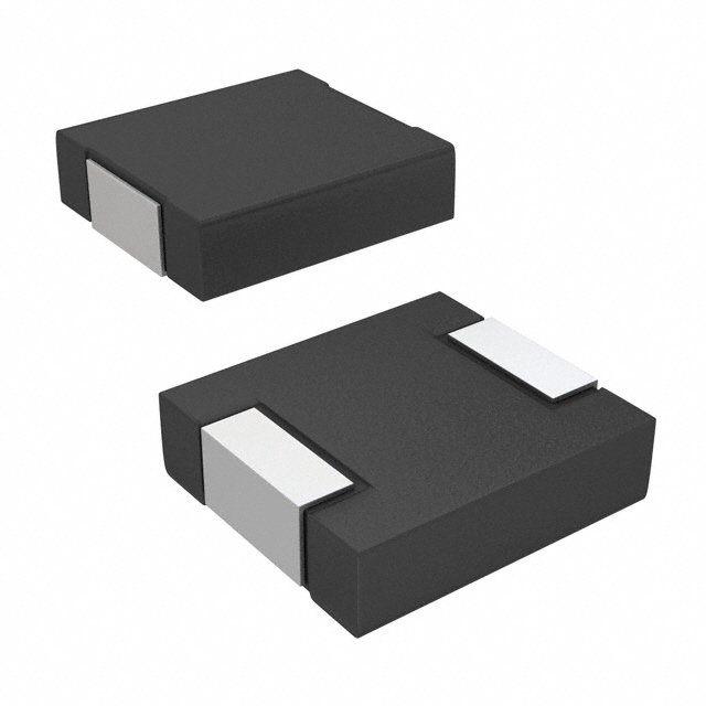
The MPIA4040R1-1R0-R is a 1 µH shielded molded inductor manufactured by Eaton - Electronics Division, rated for 3.7 A continuous current with a maximum DC resistance of 40 mOhm. This component is classified as obsolete, making equivalent and substitute parts necessary for ongoing design support and procurement continuity. The part operates across the industrial temperature range of -55°C to 125°C and meets AEC-Q200 reliability standards. Substitution is required to maintain supply chain availability and ensure design flexibility for new production runs or redesigns.
Substiute Parts
Key Parameters
| Parameter | Value | Unit |
|---|---|---|
| Inductance | 1 | µH |
| Current Rating (Continuous) | 3.7 | A |
| Current - Saturation (Isat) | 7.7 | A |
| DC Resistance (DCR) Maximum | 40 | mOhm |
| Shielding | Shielded | — |
| Type | Molded | — |
| Material - Core | Metal Composite | — |
| Tolerance | ±20% | — |
| Operating Temperature Range | -55 to 125 | °C |
| Mounting Type | Surface Mount | — |
| Size / Dimension | 0.175" L x 0.160" W (4.45mm x 4.06mm) | — |
| Height - Seated (Max) | 0.047 | inches (1.20 mm) |
| Moisture Sensitivity Level (MSL) | 1 (Unlimited) | — |
| Product Status | Obsolete | — |
| Ratings | AEC-Q200 | — |
Substitute Part Grouping Explanation
Substitution of the MPIA4040R1-1R0-R is determined by strict adherence to the following electrical and mechanical parameters:
Primary Substitution Criteria:
- Inductance value: 1 µH (exact match required)
- Inductance tolerance: ±20% (standard tolerance maintained)
- Operating temperature range: -55°C to 125°C minimum
- Mounting type: Surface Mount (SMD)
- Shielding: Shielded configuration
- Inductance test frequency: 100 kHz
Secondary Compatibility Parameters:
- Current rating: Minimum 3.7 A continuous (substitute parts may exceed this value)
- DC resistance: Maximum 40 mOhm preferred; higher values acceptable if circuit design permits
- Saturation current (Isat): Minimum 7.7 A preferred
- Physical footprint: 0.175" L x 0.160" W (4.45mm x 4.06mm) preferred; minor variations acceptable if board layout permits
- Height: 0.047" (1.20mm) maximum preferred
- Moisture sensitivity: MSL 1 (Unlimited) preferred
Substitute parts are grouped into two categories:
- Direct Electrical Equivalents – Parts matching all primary criteria with minimal parameter variation
- Functional Alternatives – Parts meeting primary criteria with acceptable parameter trade-offs in current rating, DCR, or physical dimensions
The four substitute parts listed below satisfy the primary substitution criteria and are electrically compatible with the original MPIA4040R1-1R0-R design.
Parameter Comparison
| Parameter | MPIA4040R1-1R0-R (Main) | MPIA4012V2-1R0-R | IHLP1616ABER1R0M01 | B82464G4102M000 | IHLP1616BZER1R0M01 |
|---|---|---|---|---|---|
| Manufacturer | Eaton - Electronics Division | Eaton - Electronics Division | Vishay Dale | EPCOS - TDK Electronics | Vishay Dale |
| Inductance (µH) | 1 | 1 | 1 | 1 | 1 |
| Tolerance | ±20% | ±20% | ±20% | ±20% | ±20% |
| Current Rating (A) | 3.7 | 4.3 | 4.0 | 7.5 | 3.75 |
| Current - Saturation (Isat) (A) | 7.7 | 6.5 | 7.0 | 10.0 | 8.5 |
| DC Resistance (DCR) Max (mOhm) | 40 | 46.5 | 52.5 | 7 | 37 |
| Shielding | Shielded | Shielded | Shielded | Shielded | Shielded |
| Type | Molded | Molded | Molded | Drum Core, Wirewound | Molded |
| Material - Core | Metal Composite | Metal Composite | Not specified | Ferrite | Not specified |
| Operating Temperature (°C) | -55 to 125 | -55 to 125 | -55 to 125 | -55 to 150 | -55 to 125 |
| Frequency - Self Resonant (MHz) | Not specified | 64 | 64 | 135 | 90 |
| Inductance Frequency - Test (kHz) | 100 | 100 | 100 | 100 | 100 |
| Mounting Type | Surface Mount | Surface Mount | Surface Mount | Surface Mount | Surface Mount |
| Size / Dimension (mm) | 4.45 x 4.06 | 4.95 x 4.20 | 4.45 x 4.06 | 10.40 x 10.40 | 4.45 x 4.06 |
| Height - Seated Max (mm) | 1.20 | 1.20 | 1.20 | 4.80 | 2.00 |
| Moisture Sensitivity Level (MSL) | 1 (Unlimited) | 1 (Unlimited) | 1 (Unlimited) | 1 (Unlimited) | 1 (Unlimited) |
| Product Status | Obsolete | Active | Active | Active | Active |
| RoHS Status | Not specified | RoHS Compliant | ROHS3 Compliant | ROHS3 Compliant | ROHS3 Compliant |
| Ratings | AEC-Q200 | AEC-Q200 | Not specified | AEC-Q200 | Not specified |
Engineering Selection Recommendations
MPIA4012V2-1R0-R (Eaton - Electronics Division)
This part is the primary recommended substitute. It maintains the same manufacturer (Eaton), series lineage (MPIA40-V2), and core electrical specifications. The current rating increases from 3.7 A to 4.3 A, providing design margin. DC resistance increases marginally from 40 mOhm to 46.5 mOhm, which is acceptable for most applications. The part is active in production, RoHS Compliant, and carries AEC-Q200 certification. Physical dimensions increase slightly (4.95mm x 4.20mm vs. 4.45mm x 4.06mm), requiring board layout verification. Packaging is Tape & Reel (TR), supporting high-volume manufacturing.
IHLP1616BZER1R0M01 (Vishay Dale)
This substitute offers the closest physical footprint match (4.45mm x 4.06mm) and the lowest DC resistance (37 mOhm), providing superior thermal performance. Current rating is 3.75 A, nearly identical to the original 3.7 A specification. The part is active, ROHS3 Compliant, and MSL 1. Height increases to 2.00mm (vs. 1.20mm original), requiring board clearance verification. This part is suitable for applications where thermal efficiency and compact footprint are critical.
IHLP1616ABER1R0M01 (Vishay Dale)
This part maintains identical physical dimensions (4.45mm x 4.06mm) and height (1.20mm) to the original. Current rating is 4.0 A with saturation current of 7.0 A. DC resistance is 52.5 mOhm, higher than the original specification. The part is active, ROHS3 Compliant, and REACH Unaffected. This option is suitable when physical footprint compatibility is the primary constraint.
B82464G4102M000 (EPCOS - TDK Electronics)
This part represents a functional alternative with significantly enhanced current handling (7.5 A continuous, 10 A saturation) and superior DC resistance (7 mOhm). The drum core, wirewound construction with ferrite core differs from the original molded metal composite design. Physical dimensions are substantially larger (10.40mm x 10.40mm) with height of 4.80mm, requiring significant board layout redesign. Operating temperature extends to 150°C. This part is suitable only for applications where board space permits and enhanced current capacity is required. AEC-Q200 certification is maintained.
Selection Criteria Summary:
- Preferred for direct replacement: MPIA4012V2-1R0-R (same manufacturer, active status, minimal redesign)
- Preferred for thermal optimization: IHLP1616BZER1R0M01 (lowest DCR, compact footprint)
- Preferred for footprint compatibility: IHLP1616ABER1R0M01 (identical dimensions)
- Preferred for high-current applications: B82464G4102M000 (requires board redesign)
All substitute parts are active in production, carry appropriate compliance certifications, and meet the primary electrical specifications of the obsolete MPIA4040R1-1R0-R.
Frequently Asked Questions (FAQ)
Q1: Can MPIA4012V2-1R0-R directly replace MPIA4040R1-1R0-R without circuit modification?
A: MPIA4012V2-1R0-R is electrically compatible for direct substitution in most applications. The inductance (1 µH) and tolerance (±20%) are identical. Current rating increases from 3.7 A to 4.3 A, providing design margin. DC resistance increases from 40 mOhm to 46.5 mOhm, resulting in approximately 16% higher resistive losses. Physical dimensions increase from 4.45mm x 4.06mm to 4.95mm x 4.20mm; board layout verification is required. No circuit modification is necessary if board space permits the larger footprint.
Q2: Which substitute part has the lowest DC resistance?
A: B82464G4102M000 has the lowest DC resistance at 7 mOhm maximum, compared to 40 mOhm for the original part. This represents an 82.5% reduction in resistive losses. However, this part uses a different construction type (drum core, wirewound with ferrite core) and requires significantly more board space (10.40mm x 10.40mm vs. 4.45mm x 4.06mm). IHLP1616BZER1R0M01 offers a practical alternative with 37 mOhm DCR and compatible physical dimensions.
Q3: Are all substitute parts RoHS compliant?
A: MPIA4012V2-1R0-R is RoHS Compliant. IHLP1616ABER1R0M01, B82464G4102M000, and IHLP1616BZER1R0M01 are all ROHS3 Compliant. All parts meet current environmental compliance requirements for commercial and industrial applications.
Q4: What is the impact of increased DC resistance on circuit performance?
A: DC resistance causes resistive heating in the inductor proportional to I²R. For a 3.7 A application, the original part dissipates 0.548 W (3.7² × 0.040). MPIA4012V2-1R0-R dissipates 0.637 W (3.7² × 0.0465), an increase of 16.2%. IHLP1616ABER1R0M01 dissipates 0.718 W, an increase of 31%. B82464G4102M000 dissipates only 0.096 W, a reduction of 82.5%. Thermal management and PCB copper area must be evaluated for applications sensitive to inductor heating.
Q5: Can B82464G4102M000 be used in space-constrained applications?
A: No. B82464G4102M000 measures 10.40mm x 10.40mm with a height of 4.80mm, compared to the original 4.45mm x 4.06mm footprint with 1.20mm height. This part requires approximately 5.4 times more board area and 4 times greater height clearance. It is suitable only for applications where board space is available and enhanced current capacity justifies the redesign effort.
Q6: Which substitute part is recommended for new designs?
A: MPIA4012V2-1R0-R is recommended for new designs. It is manufactured by the same company (Eaton), maintains active production status, carries AEC-Q200 certification, and is RoHS Compliant. The part provides improved current rating (4.3 A vs. 3.7 A) with acceptable DC resistance increase (46.5 mOhm vs. 40 mOhm). Packaging is Tape & Reel (TR), supporting automated assembly. Board layout modification is minimal.
Q7: What is the difference between molded and drum core, wirewound inductors?
A: Molded inductors (MPIA4040R1-1R0-R, MPIA4012V2-1R0-R, IHLP1616ABER1R0M01, IHLP1616BZER1R0M01) use a metal composite or unspecified core material with wire wound around it, then encapsulated in a molded compound. This design provides compact size and shielding. Drum core, wirewound inductors (B82464G4102M000) use a ferrite drum core with wire wound around it, offering lower DC resistance and higher current capacity but larger physical size. Selection depends on application requirements for size, current handling, and thermal performance.
Q8: Are substitute parts available in the same packaging format?
A: MPIA4012V2-1R0-R is supplied in Tape & Reel (TR) packaging, matching the original part's production packaging. IHLP1616ABER1R0M01 and IHLP1616BZER1R0M01 are supplied in Tape & Reel (TR) and Cut Tape (CT) & Digi-Reel® formats respectively. B82464G4102M000 is supplied in Tape & Reel (TR). All packaging formats support automated PCB assembly processes.
Q9: What is the saturation current (Isat) and why does it matter?
A: Saturation current is the DC current level at which the inductor's core begins to saturate, causing inductance to drop significantly. For MPIA4040R1-1R0-R, Isat is 7.7 A. Substitute parts have Isat values ranging from 6.5 A (MPIA4012V2-1R0-R) to 10 A (B82464G4102M000). In applications with current transients or peak currents, the inductor must operate below Isat to maintain stable inductance. Lower Isat values provide less margin for current spikes.
Q10: Can IHLP1616BZER1R0M01 be used if board height is limited?
A: IHLP1616BZER1R0M01 has a seated height of 2.00mm, compared to 1.20mm for the original part. If board clearance is limited to 1.20mm, this part cannot be used. However, if 2.00mm clearance is available, this part offers the advantage of lowest DC resistance (37 mOhm) and identical footprint dimensions (4.45mm x 4.06mm), making it suitable for thermal-sensitive applications.
Alternative Parts

SJ6012L2TP
Littelfuse Inc.
6 Alternative Parts

JMK107BBJ476MA-RE
Taiyo Yuden
10 Alternative Parts

GMK107BBJ475MA-T
Taiyo Yuden
5 Alternative Parts
SJ6020N2ARP
Littelfuse Inc.
3 Alternative Parts
SJ6025R2ATP
Littelfuse Inc.
4 Alternative Parts

2474-05L
API Delevan Inc.
1 Alternative Parts

4590R-684K
API Delevan Inc.
1 Alternative Parts

CM6560R-334
API Delevan Inc.
1 Alternative Parts

CM6460-104
API Delevan Inc.
1 Alternative Parts

5526-12
API Delevan Inc.
1 Alternative Parts