


Request Quote
(Ships tomorrow)
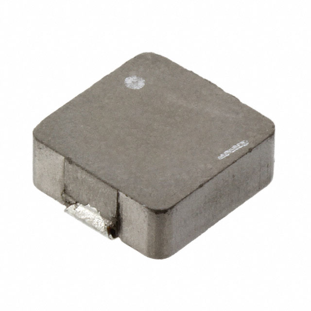
MPC1040LR56C Equivalent & Substitute Parts
Part Overview
The MPC1040LR56C is a 560 nH shielded inductor manufactured by KEMET, designed for surface mount applications requiring high current handling and low DC resistance. This ferrite core inductor is rated for 23 A continuous current with a maximum DC resistance of 1.3 mOhm and operates across the temperature range of -20°C to 120°C. The component is classified as Active product status with full RoHS3 compliance and unlimited moisture sensitivity rating (MSL 1).
Equivalent and substitute parts are identified to support procurement flexibility, inventory management, and supply chain continuity while maintaining electrical and mechanical compatibility within specified tolerance parameters.
Substiute Parts
Key Parameters
| Parameter | Value | Unit |
|---|---|---|
| Inductance | 560 | nH |
| Inductance Tolerance | ±20% | % |
| Current Rating | 23 | A |
| Current - Saturation (Isat) | 25 | A |
| DC Resistance (DCR) Maximum | 1.3 | mOhm |
| Shielding | Shielded | — |
| Core Material | Ferrite | — |
| Mounting Type | Surface Mount | — |
| Package / Case | 2-SMD, J-Lead | — |
| Physical Dimensions | 11.50 × 10.00 × 4.00 | mm (L × W × H) |
| Inductance Test Frequency | 100 | kHz |
| Operating Temperature Range | -20 to 120 | °C |
| RoHS Status | ROHS3 Compliant | — |
| Moisture Sensitivity Level | 1 (Unlimited) | — |
Substitute Part Grouping Explanation
Substitution eligibility for the MPC1040LR56C is determined by strict alignment of the following critical parameters:
Inductance Value and Tolerance: The substitute part must provide 560 nH inductance within ±20% tolerance, measured at 100 kHz test frequency.
Current Handling Capability: The substitute must support a minimum continuous current rating of 23 A with saturation current (Isat) at or above 25 A to maintain performance under transient conditions.
DC Resistance (DCR): The substitute's maximum DC resistance must not exceed 1.3 mOhm to ensure equivalent power dissipation and thermal characteristics in the application circuit.
Shielding Configuration: The substitute must be shielded to prevent electromagnetic interference and maintain the same EMI performance profile as the original component.
Package and Mounting: The substitute must use identical 2-SMD, J-Lead surface mount packaging with physical dimensions of 11.50 mm × 10.00 mm × 4.00 mm (maximum height) to ensure PCB layout compatibility without redesign.
Regulatory Compliance: The substitute must maintain RoHS3 compliance, MSL 1 rating, and REACH unaffected status to satisfy supply chain and environmental requirements.
The ETQ-P4LR56WFC from Panasonic Electronic Components meets all substitution criteria within these defined parameters.
Parameter Comparison
| Parameter | MPC1040LR56C (KEMET) | ETQ-P4LR56WFC (Panasonic) | Compatibility |
|---|---|---|---|
| Inductance | 560 nH | 560 nH | Matched |
| Inductance Tolerance | ±20% | ±20% | Matched |
| Current Rating | 23 A | 21 A | Substitute rated 2 A lower |
| DC Resistance (DCR) | 1.3 mOhm Max | 1.56 mOhm | Substitute 0.26 mOhm higher |
| Shielding | Shielded | Shielded | Matched |
| Core Material | Ferrite | Metal Composite | Different core type |
| Package / Case | 2-SMD, J-Lead | 2-SMD, J-Lead | Matched |
| Physical Dimensions | 11.50 × 10.00 × 4.00 mm | 11.50 × 10.00 × 4.00 mm | Matched |
| Inductance Test Frequency | 100 kHz | 100 kHz | Matched |
| RoHS Status | ROHS3 Compliant | ROHS3 Compliant | Matched |
| Moisture Sensitivity Level | 1 (Unlimited) | 1 (Unlimited) | Matched |
| REACH Status | REACH Unaffected | REACH Unaffected | Matched |
| Product Status | Active | Active | Matched |
Engineering Selection Recommendations
Primary Selection (MPC1040LR56C): Use the KEMET MPC1040LR56C as the primary component choice when the application requires the specified 23 A continuous current rating and 1.3 mOhm maximum DC resistance. This ferrite core inductor is Active product status with full RoHS3 compliance and unlimited MSL rating, supporting unrestricted storage and handling conditions.
Substitute Selection (ETQ-P4LR56WFC): The Panasonic ETQ-P4LR56WFC is electrically and mechanically compatible as a substitute when the application circuit can tolerate a 2 A reduction in continuous current rating (21 A versus 23 A) and a 0.26 mOhm increase in DC resistance (1.56 mOhm versus 1.3 mOhm maximum). The metal composite core construction of the Panasonic part provides equivalent shielding and inductance performance at the 100 kHz test frequency. Both components share identical package geometry, surface mount configuration, and regulatory compliance status (RoHS3, MSL 1, REACH unaffected).
Compliance Verification: Both parts maintain Active product status and full regulatory compliance. Selection between these parts should be based on application current requirements and acceptable power dissipation limits determined by the circuit design specifications.
Frequently Asked Questions (FAQ)
Q: Can the ETQ-P4LR56WFC replace the MPC1040LR56C in all applications?
A: The ETQ-P4LR56WFC is mechanically and electrically compatible for applications where the continuous current requirement does not exceed 21 A and the circuit design accommodates the 0.26 mOhm higher DC resistance. Applications requiring the full 23 A rating or lower DC resistance must use the MPC1040LR56C.
Q: What is the difference between ferrite and metal composite core materials?
A: The MPC1040LR56C uses ferrite core material, while the ETQ-P4LR56WFC uses metal composite core material. Both provide shielding and achieve the specified 560 nH inductance within ±20% tolerance at 100 kHz. Core material differences do not affect package compatibility or PCB layout requirements.
Q: Are the physical dimensions identical between these parts?
A: Yes. Both the MPC1040LR56C and ETQ-P4LR56WFC use identical 2-SMD, J-Lead packaging with dimensions of 11.50 mm length × 10.00 mm width × 4.00 mm maximum height. No PCB redesign is required for substitution.
Q: Do both parts have the same moisture sensitivity rating?
A: Yes. Both components carry MSL 1 (Unlimited) moisture sensitivity level, allowing unrestricted storage and handling without desiccant requirements or bake-out procedures.
Q: What regulatory certifications apply to both parts?
A: Both the MPC1040LR56C and ETQ-P4LR56WFC are RoHS3 compliant, REACH unaffected, and classified under ECCN EAR99 with HTSUS code 8504.50.4000.
Q: How does the 0.26 mOhm DCR difference affect circuit performance?
A: The ETQ-P4LR56WFC's 1.56 mOhm maximum DCR versus the MPC1040LR56C's 1.3 mOhm maximum DCR results in proportionally higher resistive losses. At 23 A, this represents approximately 0.6 mW additional power dissipation. Circuit thermal analysis should confirm acceptability for the specific application.
Q: What is the saturation current specification for the ETQ-P4LR56WFC?
A: The saturation current (Isat) specification for the ETQ-P4LR56WFC is not provided in the available technical parameters. The MPC1040LR56C specifies 25 A saturation current. Detailed specifications should be obtained from the manufacturer for applications requiring saturation current data.
Alternative Parts

SJ6012L2TP
Littelfuse Inc.
6 Alternative Parts

JMK107BBJ476MA-RE
Taiyo Yuden
10 Alternative Parts

GMK107BBJ475MA-T
Taiyo Yuden
5 Alternative Parts
SJ6020N2ARP
Littelfuse Inc.
3 Alternative Parts
SJ6025R2ATP
Littelfuse Inc.
4 Alternative Parts

2474-05L
API Delevan Inc.
1 Alternative Parts

4590R-684K
API Delevan Inc.
1 Alternative Parts

CM6560R-334
API Delevan Inc.
1 Alternative Parts

CM6460-104
API Delevan Inc.
1 Alternative Parts

5526-12
API Delevan Inc.
1 Alternative Parts