


Request Quote
(Ships tomorrow)
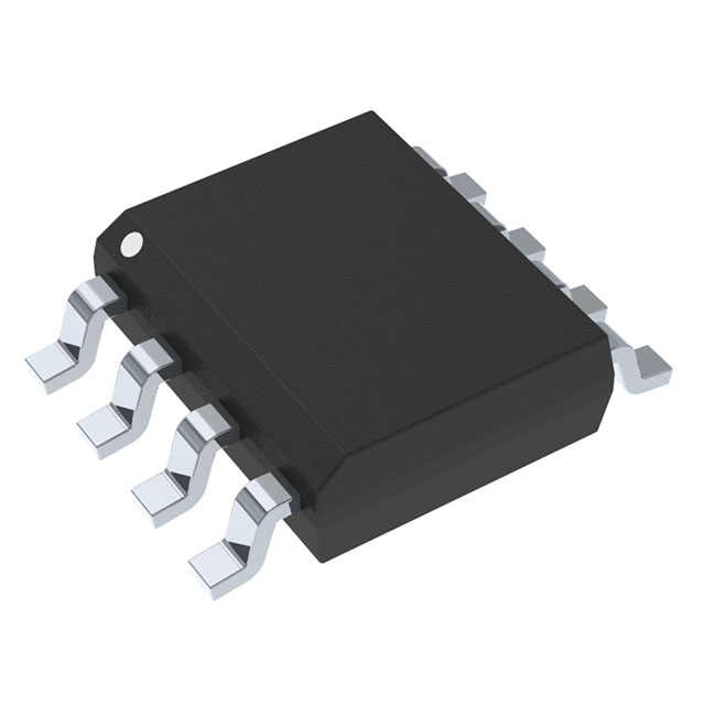
MMSF7P03HDR2G P-Channel MOSFET 30V 7A Equivalent & Substitute Parts
Part Overview
The MMSF7P03HDR2G is a P-Channel MOSFET manufactured by onsemi, rated for 30V drain-to-source voltage and 7A continuous drain current in a surface mount 8-SOIC package. This device is classified as obsolete, making identification of equivalent and substitute parts essential for ongoing design support and production continuity. Substitute parts must maintain electrical compatibility across voltage ratings, current handling, and thermal characteristics while accommodating the same package footprint and mounting requirements.
Substiute Parts
Key Parameters
| Parameter | Value | Unit |
|---|---|---|
| Drain-to-Source Voltage (Vdss) | 30 | V |
| Continuous Drain Current (Id) @ 25°C | 7 | A |
| RDS(on) Max @ Id, Vgs | 35 mOhm @ 5.3A, 10V | mOhm |
| Gate Threshold Voltage (Vgs(th)) Max @ Id | 1 | V @ 250µA |
| Gate Charge (Qg) Max @ Vgs | 75.8 | nC @ 6V |
| Power Dissipation Max | 2.5 | W |
| Operating Temperature Range | -55 to 150 | °C |
| Package Type | 8-SOIC | Surface Mount |
| Moisture Sensitivity Level | 1 | Unlimited |
Substitute Part Grouping Explanation
Substitution eligibility for the MMSF7P03HDR2G is determined by the following criteria:
Mandatory Matching Parameters:
- Drain-to-Source Voltage (Vdss): 30V minimum
- FET Type: P-Channel
- Technology: MOSFET (Metal Oxide)
- Package: 8-SOIC surface mount
- Mounting Type: Surface Mount
- Operating Temperature Range: -55°C to 150°C minimum
- Gate Voltage Rating (Vgs Max): ±20V
Allowable Variation Parameters:
- Continuous Drain Current (Id): Equal to or greater than 7A
- RDS(on) Max: Equal to or lower than 35 mOhm (lower values indicate improved performance)
- Gate Charge (Qg): Lower values acceptable (reduced switching losses)
- Power Dissipation: Equal to or greater than 2.5W
- Input Capacitance (Ciss): Variation acceptable within device design parameters
All substitute parts listed maintain identical voltage ratings, package geometry, and thermal operating range. Variations in current handling and on-resistance reflect different manufacturing processes and design generations, all of which are electrically compatible with the original specification.
Parameter Comparison
| Parameter | MMSF7P03HDR2G (onsemi) | NTMS4177PR2G (onsemi) | SI4431CDY-T1-E3 (Vishay) | AO4449 (Alpha & Omega) |
|---|---|---|---|---|
| Drain-to-Source Voltage (Vdss) | 30V | 30V | 30V | 30V |
| Continuous Drain Current (Id) @ 25°C | 7A | 6.6A | 9A | 7A |
| RDS(on) Max @ Vgs 10V | 35 mOhm @ 5.3A | 12 mOhm @ 11.4A | 32 mOhm @ 7A | 34 mOhm @ 7A |
| Gate Threshold Voltage (Vgs(th)) Max | 1V @ 250µA | 2.5V @ 250µA | 2.5V @ 250µA | 2.4V @ 250µA |
| Gate Charge (Qg) Max @ Vgs | 75.8 nC @ 6V | 55 nC @ 10V | 38 nC @ 10V | 16 nC @ 10V |
| Power Dissipation Max | 2.5W | 840 mW | 4.2W | 3.1W |
| Operating Temperature Range | -55 to 150°C | -55 to 150°C | -55 to 150°C | -55 to 150°C |
| Package Type | 8-SOIC | 8-SOIC | 8-SOIC | 8-SOIC |
| Product Status | Obsolete | Active | Active | Not For New Designs |
| Moisture Sensitivity Level | 1 (Unlimited) | 1 (Unlimited) | 1 (Unlimited) | 1 (Unlimited) |
| REACH Status | REACH Unaffected | REACH Unaffected | REACH Unaffected | REACH Unaffected |
Engineering Selection Recommendations
NTMS4177PR2G (onsemi)
This substitute is manufactured by the same supplier as the original MMSF7P03HDR2G. The device maintains 30V Vdss rating and 6.6A continuous drain current, meeting the minimum current requirement. The NTMS4177PR2G features improved RDS(on) performance at 12 mOhm and reduced gate charge at 55 nC, resulting in lower switching losses and improved thermal efficiency. Product status is Active, ensuring long-term availability and manufacturing support. RoHS3 compliance provides regulatory alignment for new production. This part is recommended for direct replacement in existing designs.
SI4431CDY-T1-E3 (Vishay Siliconix)
This substitute offers the highest current rating at 9A continuous drain current, exceeding the original 7A specification. The device maintains 30V Vdss and operates across the identical temperature range. The SI4431CDY-T1-E3 features the lowest gate charge at 38 nC and improved RDS(on) at 32 mOhm, delivering superior switching performance and thermal characteristics. The TrenchFET® series designation indicates advanced manufacturing technology. Product status is Active with RoHS3 compliance. This part is suitable for applications requiring enhanced current handling or improved thermal performance.
AO4449 (Alpha & Omega Semiconductor Inc.)
This substitute matches the original 7A continuous drain current specification and maintains 30V Vdss rating. The AO4449 features the lowest gate charge at 16 nC and RDS(on) at 34 mOhm, providing excellent switching efficiency. However, product status is classified as Not For New Designs, limiting its suitability for new production programs. This part is applicable only for legacy system maintenance or repair applications where existing inventory exists.
Frequently Asked Questions (FAQ)
Q: Can NTMS4177PR2G replace MMSF7P03HDR2G in all applications?
A: NTMS4177PR2G is electrically compatible with MMSF7P03HDR2G across all specified parameters. The 6.6A continuous drain current rating meets the 7A requirement of the original device. Identical 30V Vdss, ±20V Vgs maximum, and 8-SOIC package ensure direct substitution. The improved RDS(on) and reduced gate charge provide performance benefits without circuit modification.
Q: What is the primary difference between SI4431CDY-T1-E3 and the original MMSF7P03HDR2G?
A: SI4431CDY-T1-E3 provides higher continuous drain current at 9A versus 7A, lower gate charge at 38 nC versus 75.8 nC, and improved RDS(on) at 32 mOhm versus 35 mOhm. All other electrical parameters, including 30V Vdss, ±20V Vgs, and 8-SOIC package, remain identical. These differences represent manufacturing technology advancement rather than functional incompatibility.
Q: Why is AO4449 marked as Not For New Designs?
A: Product status classification reflects the manufacturer's commitment to long-term support and production roadmap. AO4449 remains electrically compatible and functionally equivalent to MMSF7P03HDR2G. This designation indicates the manufacturer recommends alternative parts for new design programs, though the device is suitable for legacy system support and repair applications.
Q: Are all substitute parts available in the same packaging format?
A: All substitute parts are supplied in 8-SOIC surface mount packages with identical 0.154" (3.90mm) width. Packaging options vary by supplier: NTMS4177PR2G is available in Cut Tape and Digi-Reel formats, SI4431CDY-T1-E3 in Tape & Reel format, and AO4449 in Cut Tape and Digi-Reel formats. PCB footprint compatibility is maintained across all substitutes.
Q: What is the significance of Moisture Sensitivity Level 1 (Unlimited)?
A: MSL 1 (Unlimited) indicates the device has no moisture sensitivity restrictions. Storage and handling do not require controlled humidity environments or desiccant packaging. All listed substitute parts carry identical MSL 1 classification, ensuring equivalent handling and storage requirements.
Q: How do gate charge differences affect circuit performance?
A: Gate charge (Qg) determines the energy required to switch the MOSFET on and off. Lower gate charge reduces switching losses and allows faster switching transitions. NTMS4177PR2G at 55 nC, SI4431CDY-T1-E3 at 38 nC, and AO4449 at 16 nC all represent improvements over the original 75.8 nC specification, resulting in reduced power dissipation and improved thermal performance in switching applications.
Q: Are all substitute parts RoHS compliant?
A: NTMS4177PR2G, SI4431CDY-T1-E3, and AO4449 are all RoHS3 compliant. The original MMSF7P03HDR2G does not specify RoHS status. All parts maintain REACH Unaffected status, confirming compliance with environmental regulations. This ensures regulatory alignment for production and distribution in regulated markets.
Q: Can these parts be used interchangeably in existing PCB designs?
A: Yes. All substitute parts maintain identical 8-SOIC package geometry and pin configuration. PCB footprints, solder pad layouts, and component placement remain unchanged. No circuit board redesign or layout modification is required for substitution. Electrical parameter variations are within acceptable ranges for P-Channel MOSFET applications.
Alternative Parts

SJ6012L2TP
Littelfuse Inc.
6 Alternative Parts

JMK107BBJ476MA-RE
Taiyo Yuden
10 Alternative Parts

GMK107BBJ475MA-T
Taiyo Yuden
5 Alternative Parts
SJ6020N2ARP
Littelfuse Inc.
3 Alternative Parts
SJ6025R2ATP
Littelfuse Inc.
4 Alternative Parts

2474-05L
API Delevan Inc.
1 Alternative Parts

4590R-684K
API Delevan Inc.
1 Alternative Parts

CM6560R-334
API Delevan Inc.
1 Alternative Parts

CM6460-104
API Delevan Inc.
1 Alternative Parts

5526-12
API Delevan Inc.
1 Alternative Parts