


Request Quote
(Ships tomorrow)
MLF2012K560MT Equivalent & Substitute Parts
Part Overview
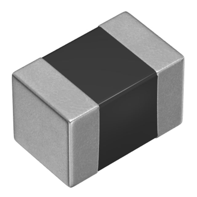
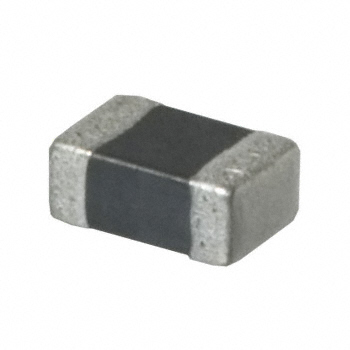
The MLF2012K560MT is a 56 µH shielded multilayer inductor manufactured by TDK Corporation, designed for surface mount applications in the 0805 (2012 Metric) package. This component features a 4 mA current rating, 1.8Ω DC resistance, and operates across the temperature range of -55°C to 125°C. The part is designated as "Not For New Designs," indicating its status as a legacy component. Identifying equivalent substitute parts is necessary to ensure design continuity, maintain supply chain flexibility, and support ongoing production requirements for existing applications.
Substiute Parts
Key Parameters
| Parameter | Value |
|---|---|
| Inductance | 56 µH |
| Current Rating | 4 mA |
| DC Resistance (DCR) | 1.8Ω |
| Package / Case | 0805 (2012 Metric) |
| Shielding | Shielded |
| Material - Core | Ferrite |
| Operating Temperature Range | -55°C ~ 125°C |
| RoHS Status | ROHS3 Compliant |
Substitute Part Grouping Explanation
Substitution eligibility for the MLF2012K560MT is determined by the following critical parameters:
Inductance value must remain 56 µH to maintain circuit performance and frequency response characteristics. Current rating must be 4 mA or greater to support the intended application load. Package and case dimensions must conform to 0805 (2012 Metric) specifications to ensure mechanical compatibility with existing PCB layouts. Shielding type must be shielded to maintain electromagnetic isolation properties. Core material must be ferrite to preserve inductance stability and frequency characteristics. RoHS3 compliance is required for regulatory alignment.
DC resistance and operating temperature range represent secondary parameters that may vary within acceptable engineering tolerances, provided the primary parameters remain constant.
Parameter Comparison
| Parameter | MLF2012K560MT (Main Part) | MLF2012K560KT000 (Substitute) |
|---|---|---|
| Manufacturer | TDK Corporation | TDK Corporation |
| Inductance | 56 µH | 56 µH |
| Inductance Tolerance | ±20% | ±10% |
| Current Rating (Amps) | 4 mA | 4 mA |
| DC Resistance (DCR) | 1.8Ω | 2.8Ω Max |
| Q @ Freq | 35 @ 2MHz | 35 @ 2MHz |
| Frequency - Self Resonant | 10MHz | 10MHz |
| Operating Temperature | -55°C ~ 125°C | -40°C ~ 85°C |
| Package / Case | 0805 (2012 Metric) | 0805 (2012 Metric) |
| Size / Dimension | 0.079" L x 0.049" W (2.00mm x 1.25mm) | 0.079" L x 0.049" W (2.00mm x 1.25mm) |
| Height - Seated (Max) | 0.057" (1.45mm) | 0.057" (1.45mm) |
| Shielding | Shielded | Shielded |
| Material - Core | Ferrite | Ferrite |
| RoHS Status | ROHS3 Compliant | ROHS3 Compliant |
| Moisture Sensitivity Level (MSL) | 1 (Unlimited) | 1 (Unlimited) |
| REACH Status | REACH Unaffected | REACH Unaffected |
| Product Status | Not For New Designs | Active |
| Packaging Type | Tape & Reel (TR) | Cut Tape (CT) |
Engineering Selection Recommendations
The MLF2012K560KT000 is the manufacturer-recommended substitute for the MLF2012K560MT. Both components are manufactured by TDK Corporation and share identical inductance values, current ratings, package dimensions, and core material specifications. The substitute part maintains full mechanical and electrical compatibility with the original design.
The MLF2012K560KT000 carries Active product status, ensuring continued availability and long-term supply chain support compared to the legacy MLF2012K560MT. Both parts meet ROHS3 compliance and REACH regulatory requirements, supporting equivalent environmental and regulatory standards.
The primary differences between the parts are inductance tolerance (±10% versus ±20%), DC resistance (2.8Ω Max versus 1.8Ω), and operating temperature range (-40°C ~ 85°C versus -55°C ~ 125°C). These variations must be evaluated against specific circuit requirements to determine suitability for the intended application.
Frequently Asked Questions (FAQ)
Q: Can MLF2012K560KT000 be used as a direct replacement for MLF2012K560MT?
A: The MLF2012K560KT000 meets the primary substitution criteria: identical inductance value (56 µH), current rating (4 mA), package dimensions (0805 / 2012 Metric), shielding type (shielded), and core material (ferrite). Compatibility depends on whether the application can tolerate the higher DC resistance (2.8Ω Max versus 1.8Ω) and narrower operating temperature range (-40°C ~ 85°C versus -55°C ~ 125°C).
Q: What are the key differences in DC resistance between these parts?
A: The MLF2012K560MT specifies 1.8Ω DC resistance, while the MLF2012K560KT000 specifies 2.8Ω maximum. This 1Ω difference may affect power dissipation and thermal performance in current-sensitive applications. Circuit analysis is required to determine if this variance is acceptable.
Q: How do the inductance tolerances differ?
A: The MLF2012K560MT has ±20% inductance tolerance, while the MLF2012K560KT000 has ±10% tolerance. The tighter tolerance of the substitute part provides improved inductance consistency and may benefit frequency-dependent circuit performance.
Q: Are the package dimensions identical?
A: Yes. Both parts use the 0805 (2012 Metric) package with dimensions of 0.079" L x 0.049" W (2.00mm x 1.25mm) and maximum seated height of 0.057" (1.45mm). PCB layout compatibility is maintained.
Q: What is the difference between Tape & Reel and Cut Tape packaging?
A: The MLF2012K560MT is supplied in Tape & Reel (TR) format for automated assembly processes, while the MLF2012K560KT000 is supplied in Cut Tape (CT) format. Both packaging types are suitable for surface mount assembly; selection depends on production equipment and volume requirements.
Q: Do both parts meet the same regulatory standards?
A: Yes. Both the MLF2012K560MT and MLF2012K560KT000 are ROHS3 compliant and REACH unaffected, meeting equivalent environmental and regulatory requirements.
Alternative Parts

SJ6012L2TP
Littelfuse Inc.
6 Alternative Parts

JMK107BBJ476MA-RE
Taiyo Yuden
10 Alternative Parts

GMK107BBJ475MA-T
Taiyo Yuden
5 Alternative Parts
SJ6020N2ARP
Littelfuse Inc.
3 Alternative Parts
SJ6025R2ATP
Littelfuse Inc.
4 Alternative Parts

2474-05L
API Delevan Inc.
1 Alternative Parts

4590R-684K
API Delevan Inc.
1 Alternative Parts

CM6560R-334
API Delevan Inc.
1 Alternative Parts

CM6460-104
API Delevan Inc.
1 Alternative Parts

5526-12
API Delevan Inc.
1 Alternative Parts