


Request Quote
(Ships tomorrow)
MLF2012E8R2MTD25 Equivalent & Substitute Parts
Part Overview
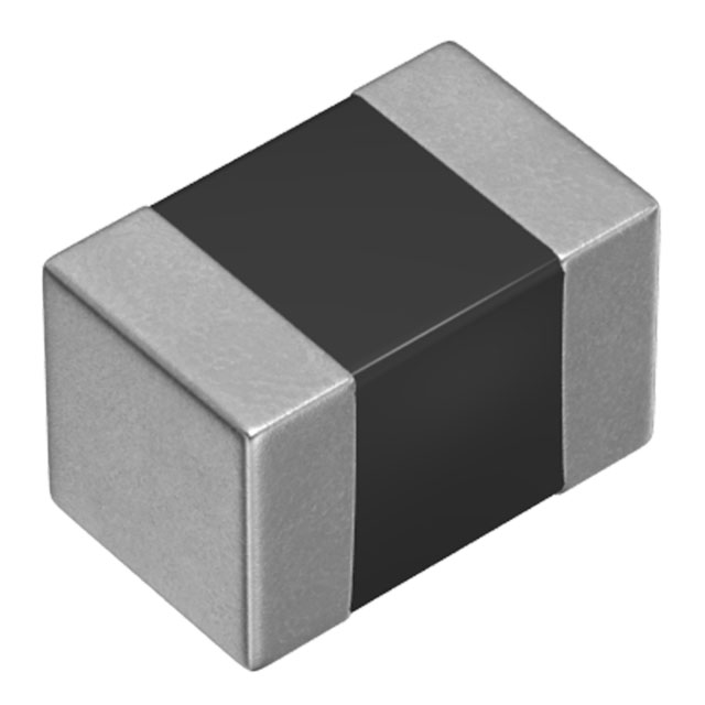
The MLF2012E8R2MTD25 is an 8.2 µH shielded multilayer ferrite inductor manufactured by TDK Corporation, designed for surface mount applications in the 0805 (2012 Metric) package. This component is rated for 15 mA maximum current with a maximum DC resistance of 700mOhm and operates across the temperature range of -55°C to 125°C. The part is currently in active production status and maintains full RoHS3 compliance with unlimited moisture sensitivity rating (MSL 1). Equivalent substitute parts may be required due to supply chain constraints, inventory availability, or specific design optimization needs while maintaining electrical and mechanical compatibility.
Substiute Parts
Key Parameters
| Parameter | Value |
|---|---|
| Inductance | 8.2 µH |
| Inductance Tolerance | ±20% |
| Current Rating | 15 mA |
| DC Resistance (DCR) | 700mOhm Max |
| Package / Case | 0805 (2012 Metric) |
| Shielding | Shielded |
| Core Material | Ferrite |
| Operating Temperature Range | -55°C ~ 125°C |
| Mounting Type | Surface Mount |
| RoHS Status | ROHS3 Compliant |
Substitute Part Grouping Explanation
Substitution eligibility for the MLF2012E8R2MTD25 is determined by the following critical parameters:
- Inductance Value: Must be 8.2 µH (tolerance variations are acceptable within design margin)
- Current Rating: Minimum 15 mA required
- Package / Case: Must be 0805 (2012 Metric) for PCB footprint compatibility
- Mounting Type: Surface mount only
- Core Material: Ferrite shielded construction
- Operating Temperature Range: Must support -55°C ~ 125°C minimum
- DC Resistance: Lower or equal DCR values are acceptable; higher values may impact circuit performance
The CV201210-8R2K from Bourns Inc. meets all substitution criteria with matching inductance, current rating, package dimensions, and operating temperature specifications. The substitute part demonstrates improved DC resistance characteristics (1.1Ohm Max vs. 700mOhm Max) and tighter inductance tolerance (±10% vs. ±20%), making it functionally compatible for direct replacement applications.
Parameter Comparison
| Parameter | MLF2012E8R2MTD25 (TDK) | CV201210-8R2K (Bourns) |
|---|---|---|
| Inductance | 8.2 µH | 8.2 µH |
| Inductance Tolerance | ±20% | ±10% |
| Current Rating (Amps) | 15 mA | 15 mA |
| DC Resistance (DCR) | 700mOhm Max | 1.1Ohm Max |
| Q @ Freq | 50 @ 4MHz | 45 @ 4MHz |
| Frequency - Self Resonant | 35MHz | 26MHz |
| Package / Case | 0805 (2012 Metric) | 0805 (2012 Metric) |
| Size / Dimension | 0.079" L x 0.049" W (2.00mm x 1.25mm) | 0.079" L x 0.049" W (2.00mm x 1.25mm) |
| Height - Seated (Max) | 0.057" (1.45mm) | 0.057" (1.45mm) |
| Operating Temperature | -55°C ~ 125°C | -55°C ~ 125°C |
| Mounting Type | Surface Mount | Surface Mount |
| RoHS Status | ROHS3 Compliant | ROHS3 Compliant |
| Moisture Sensitivity Level (MSL) | 1 (Unlimited) | 1 (Unlimited) |
| REACH Status | REACH Unaffected | REACH Unaffected |
Engineering Selection Recommendations
Both the MLF2012E8R2MTD25 and CV201210-8R2K are active production components with full RoHS3 compliance and REACH unaffected status. The MLF2012E8R2MTD25 is manufactured by TDK Corporation and the CV201210-8R2K by Bourns Inc., both established suppliers in the passive component industry. Selection between these parts should be based on availability, lead time requirements, and specific circuit performance needs. The CV201210-8R2K offers tighter inductance tolerance and lower DC resistance, which may provide performance advantages in applications sensitive to resistance losses. Both components are certified for the same operating temperature range and moisture sensitivity classification, ensuring equivalent reliability in standard industrial and commercial applications.
Frequently Asked Questions (FAQ)
Q: Can the CV201210-8R2K directly replace the MLF2012E8R2MTD25 on the PCB?
A: Yes. Both components use the identical 0805 (2012 Metric) package with matching footprint dimensions (2.00mm L x 1.25mm W) and maximum seated height (1.45mm). No PCB layout modifications are required for direct substitution.
Q: What is the impact of the different DC resistance values?
A: The CV201210-8R2K has a maximum DC resistance of 1.1Ohm compared to 700mOhm for the MLF2012E8R2MTD25. In circuits where inductor resistance contributes to signal loss or heat generation, the lower resistance of the TDK part may be preferable. For most general-purpose filtering and impedance matching applications, both values are functionally acceptable.
Q: Are there differences in high-frequency performance?
A: The MLF2012E8R2MTD25 has a self-resonant frequency of 35MHz versus 26MHz for the CV201210-8R2K. The TDK part maintains higher Q factor (50 vs. 45 at 4MHz). For applications operating near or above 26MHz, the TDK part may provide better performance characteristics.
Q: Do both parts meet the same compliance requirements?
A: Yes. Both components are ROHS3 compliant, REACH unaffected, and classified as MSL 1 (unlimited moisture sensitivity). They are suitable for equivalent use in applications requiring these certifications.
Q: What is the inductance tolerance difference impact?
A: The CV201210-8R2K offers ±10% tolerance versus ±20% for the MLF2012E8R2MTD25. Tighter tolerance may be beneficial in precision filter designs or impedance-critical applications where inductance variation directly affects circuit performance.
Alternative Parts

SJ6012L2TP
Littelfuse Inc.
6 Alternative Parts

JMK107BBJ476MA-RE
Taiyo Yuden
10 Alternative Parts

GMK107BBJ475MA-T
Taiyo Yuden
5 Alternative Parts
SJ6020N2ARP
Littelfuse Inc.
3 Alternative Parts
SJ6025R2ATP
Littelfuse Inc.
4 Alternative Parts

2474-05L
API Delevan Inc.
1 Alternative Parts

4590R-684K
API Delevan Inc.
1 Alternative Parts

CM6560R-334
API Delevan Inc.
1 Alternative Parts

CM6460-104
API Delevan Inc.
1 Alternative Parts

5526-12
API Delevan Inc.
1 Alternative Parts