


Request Quote
(Ships tomorrow)
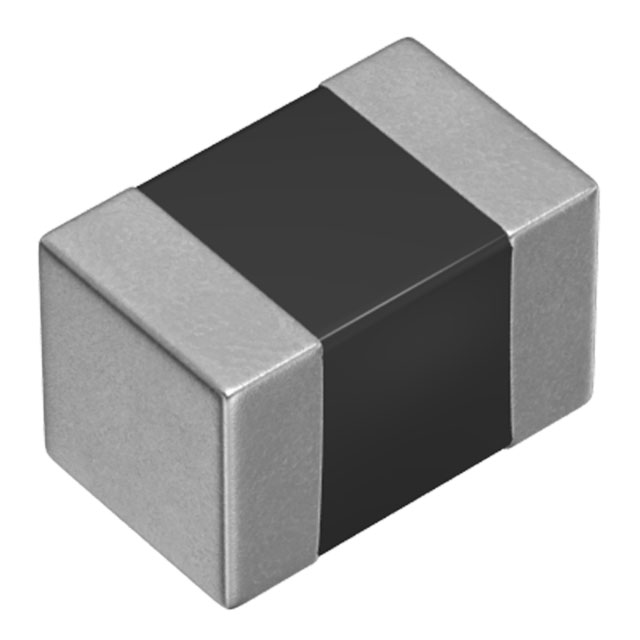
MLF2012DR82KTD25 Equivalent & Substitute Parts
Part Overview
The MLF2012DR82KTD25 is a 820 nH shielded multilayer inductor manufactured by TDK Corporation, designed for surface mount applications in the 0805 (2012 Metric) package. This component is rated for 150 mA maximum current with a maximum DC resistance of 650 mOhm and operates across the temperature range of -55°C to 125°C. The part maintains Active product status and carries AEC-Q200 automotive-grade certification. Equivalent substitute parts are identified to provide design flexibility, supply chain alternatives, and component availability options while maintaining electrical and mechanical compatibility.
Substiute Parts
Key Parameters
| Parameter | Value |
|---|---|
| Inductance | 820 nH |
| Inductance Tolerance | ±10% |
| Current Rating | 150 mA |
| DC Resistance (DCR) | 650 mOhm Max |
| Shielding | Shielded |
| Core Material | Ferrite |
| Package / Case | 0805 (2012 Metric) |
| Mounting Type | Surface Mount |
| Operating Temperature Range | -55°C to 125°C |
| Q @ Frequency | 25 @ 25 MHz |
| RoHS Status | ROHS3 Compliant |
| Moisture Sensitivity Level | 1 (Unlimited) |
Substitute Part Grouping Explanation
Substitute parts for the MLF2012DR82KTD25 are qualified based on the following critical parameters that determine functional and mechanical compatibility:
Inductance value and tolerance must match exactly at 820 nH ±10% to ensure circuit performance and frequency response characteristics remain within design specifications.
Current rating must be equal to or greater than 150 mA to support the intended application load without saturation or thermal degradation.
Package and case dimensions must conform to 0805 (2012 Metric) specifications to ensure PCB footprint compatibility and automated assembly compatibility.
Shielding type must be shielded to maintain electromagnetic isolation and prevent interference in sensitive circuit environments.
Core material must be ferrite to maintain consistent inductance characteristics across the operating frequency range.
Operating temperature range must encompass -55°C to 125°C to support the full environmental operating conditions.
Surface mount mounting type is required for compatibility with standard PCB assembly processes.
The substitute part CV201210-R82K from Bourns Inc. meets all critical substitution criteria within these parameters.
Parameter Comparison
| Parameter | MLF2012DR82KTD25 (TDK) | CV201210-R82K (Bourns) |
|---|---|---|
| Inductance | 820 nH | 820 nH |
| Inductance Tolerance | ±10% | ±10% |
| Current Rating (Amps) | 150 mA | 150 mA |
| DC Resistance (DCR) | 650 mOhm Max | 1 Ohm Max |
| Shielding | Shielded | Shielded |
| Core Material | Ferrite | Ferrite |
| Q @ Frequency | 25 @ 25 MHz | 25 @ 25 MHz |
| Package / Case | 0805 (2012 Metric) | 0805 (2012 Metric) |
| Size / Dimension | 0.079" L x 0.049" W (2.00mm x 1.25mm) | 0.079" L x 0.049" W (2.00mm x 1.25mm) |
| Height - Seated (Max) | 0.057" (1.45mm) | 0.057" (1.45mm) |
| Mounting Type | Surface Mount | Surface Mount |
| Operating Temperature Range | -55°C to 125°C | -55°C to 125°C |
| RoHS Status | ROHS3 Compliant | ROHS3 Compliant |
| Moisture Sensitivity Level | 1 (Unlimited) | 1 (Unlimited) |
Engineering Selection Recommendations
Both the MLF2012DR82KTD25 and CV201210-R82K maintain Active product status and carry ROHS3 compliance certification, confirming current manufacturing availability and environmental regulatory adherence. The MLF2012DR82KTD25 carries AEC-Q200 automotive-grade certification, which provides additional qualification for automotive and high-reliability applications. The CV201210-R82K does not list AEC-Q200 certification in the provided specifications.
The primary electrical difference between these parts is DC resistance: the MLF2012DR82KTD25 specifies 650 mOhm maximum, while the CV201210-R82K specifies 1 Ohm maximum. This difference must be evaluated against circuit design requirements, particularly in applications where resistive losses directly impact efficiency or thermal performance.
Selection between these parts should be based on specific application requirements regarding DC resistance tolerance, automotive certification requirements, and supply chain availability.
Frequently Asked Questions (FAQ)
Q: Can CV201210-R82K be used as a direct replacement for MLF2012DR82KTD25?
A: Both parts share identical inductance values, current ratings, package dimensions, and operating temperature ranges. The primary difference is DC resistance specification: MLF2012DR82KTD25 at 650 mOhm maximum versus CV201210-R82K at 1 Ohm maximum. Substitution is permissible only if circuit design tolerates the higher DC resistance value of the Bourns part.
Q: What is the significance of the 0805 (2012 Metric) package designation?
A: The 0805 (2012 Metric) package specifies the physical dimensions and PCB footprint for surface mount assembly. Both parts conform to identical package specifications: 2.00mm length, 1.25mm width, and 1.45mm maximum seated height. This ensures mechanical and assembly compatibility on standard PCB layouts.
Q: Are both parts suitable for automotive applications?
A: The MLF2012DR82KTD25 carries AEC-Q200 automotive-grade certification. The CV201210-R82K does not list AEC-Q200 certification in available specifications. For automotive applications requiring AEC-Q200 qualification, the MLF2012DR82KTD25 is the specified choice.
Q: How do the Q factor specifications compare?
A: Both parts specify Q @ 25 MHz = 25, indicating identical quality factor performance at the test frequency. This parameter is consistent across both components.
Q: What does ROHS3 compliance indicate?
A: ROHS3 compliance confirms that both parts meet Restriction of Hazardous Substances Directive requirements, restricting the use of specific hazardous materials in electrical and electronic equipment. Both the MLF2012DR82KTD25 and CV201210-R82K are ROHS3 compliant.
Alternative Parts

SJ6012L2TP
Littelfuse Inc.
6 Alternative Parts

JMK107BBJ476MA-RE
Taiyo Yuden
10 Alternative Parts

GMK107BBJ475MA-T
Taiyo Yuden
5 Alternative Parts
SJ6020N2ARP
Littelfuse Inc.
3 Alternative Parts
SJ6025R2ATP
Littelfuse Inc.
4 Alternative Parts

2474-05L
API Delevan Inc.
1 Alternative Parts

4590R-684K
API Delevan Inc.
1 Alternative Parts

CM6560R-334
API Delevan Inc.
1 Alternative Parts

CM6460-104
API Delevan Inc.
1 Alternative Parts

5526-12
API Delevan Inc.
1 Alternative Parts