


Request Quote
(Ships tomorrow)
MLF2012DR10MTD25 Equivalent & Substitute Parts
Part Overview
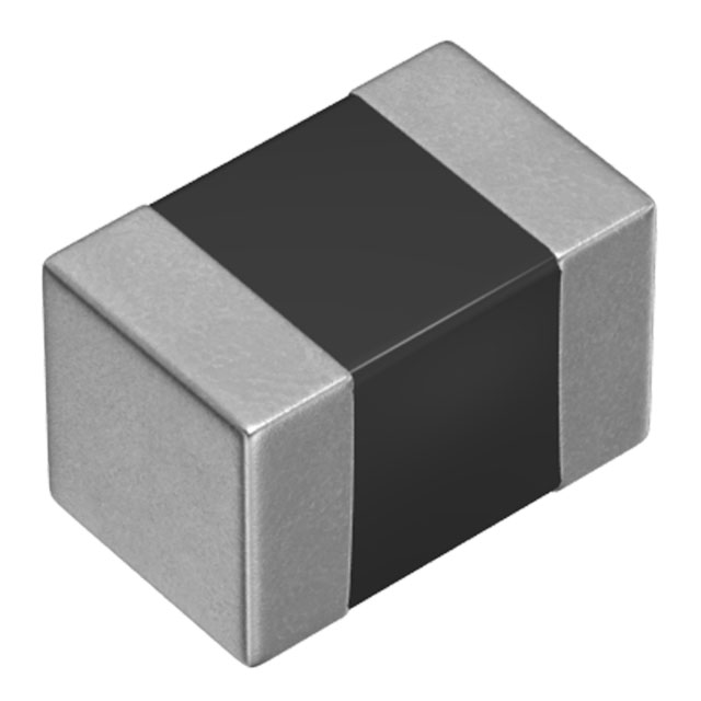
The MLF2012DR10MTD25 is a 100 nH shielded multilayer inductor manufactured by TDK Corporation, designed for surface mount applications in the 0805 (2012 Metric) package. This component is rated for 300 mA continuous current with a maximum DC resistance of 150 mOhm and operates across the temperature range of -55°C to 125°C. The part is currently in active production status and maintains full RoHS3 compliance.
Substitute parts become necessary when the primary component experiences supply constraints, extended lead times, or when design flexibility allows for alternative manufacturers while maintaining functional equivalence within specified electrical and mechanical tolerances.
Substiute Parts
Key Parameters
| Parameter | Value |
|---|---|
| Inductance | 100 nH |
| Inductance Tolerance | ±20% |
| Current Rating | 300 mA |
| DC Resistance (DCR) | 150 mOhm Max |
| Package / Case | 0805 (2012 Metric) |
| Shielding | Shielded |
| Core Material | Ferrite |
| Operating Temperature Range | -55°C to 125°C |
| Mounting Type | Surface Mount |
| RoHS Status | ROHS3 Compliant |
Substitute Part Grouping Explanation
Substitution eligibility for the MLF2012DR10MTD25 is determined by the following critical parameters:
- Inductance Value: Must be 100 nH (exact match required)
- Package / Case: Must be 0805 (2012 Metric) for PCB footprint compatibility
- Shielding Type: Must be shielded to maintain electromagnetic isolation
- Core Material: Must be ferrite for consistent performance characteristics
- Mounting Type: Must be surface mount
- Operating Temperature Range: Must support -55°C to 125°C minimum
- Current Rating: Must support minimum 250 mA (substitute may have lower rating if application permits)
- DC Resistance: Substitute DCR must not exceed 300 mOhm (higher than primary part is acceptable if within application limits)
The CV201210-R10K from Bourns Inc. meets all substitution criteria within these allowable parameters.
Parameter Comparison
| Parameter | MLF2012DR10MTD25 (TDK) | CV201210-R10K (Bourns) | Compatibility |
|---|---|---|---|
| Inductance | 100 nH | 100 nH | Exact Match |
| Inductance Tolerance | ±20% | ±10% | Compatible (Bourns tighter) |
| Current Rating (Amps) | 300 mA | 250 mA | Bourns rated lower |
| DC Resistance (DCR) | 150 mOhm Max | 300 mOhm Max | Bourns higher DCR |
| Q @ Freq | 20 @ 25MHz | 20 @ 25MHz | Exact Match |
| Shielding | Shielded | Shielded | Exact Match |
| Core Material | Ferrite | Ferrite | Exact Match |
| Operating Temperature | -55°C ~ 125°C | -55°C ~ 125°C | Exact Match |
| Package / Case | 0805 (2012 Metric) | 0805 (2012 Metric) | Exact Match |
| Mounting Type | Surface Mount | Surface Mount | Exact Match |
| RoHS Status | ROHS3 Compliant | ROHS3 Compliant | Exact Match |
| MSL Rating | 1 (Unlimited) | 1 (Unlimited) | Exact Match |
Engineering Selection Recommendations
Both the MLF2012DR10MTD25 and CV201210-R10K are active production components with full RoHS3 compliance and REACH unaffected status. Selection between these parts should be based on application-specific current requirements and DC resistance tolerance.
The TDK MLF2012DR10MTD25 provides a 300 mA current rating with 150 mOhm maximum DC resistance, suitable for applications requiring higher current capacity and lower resistive losses.
The Bourns CV201210-R10K offers a 250 mA current rating with 300 mOhm maximum DC resistance and tighter inductance tolerance (±10% versus ±20%), making it suitable for applications where inductance precision is prioritized and current requirements do not exceed 250 mA.
Both components share identical package dimensions, operating temperature range, shielding characteristics, and core material composition, ensuring mechanical and thermal compatibility in PCB assembly.
Frequently Asked Questions (FAQ)
Q: Can the CV201210-R10K replace the MLF2012DR10MTD25 in all applications?
A: Substitution is valid only if the application current requirement does not exceed 250 mA and the higher DC resistance of 300 mOhm (versus 150 mOhm) is acceptable for the circuit design. Both parts share identical inductance values, package dimensions, and operating temperature ranges.
Q: What is the impact of the different DC resistance values?
A: The MLF2012DR10MTD25 has 150 mOhm maximum DCR while the CV201210-R10K has 300 mOhm maximum DCR. Higher DC resistance increases resistive losses in the inductor, which may affect circuit efficiency and thermal performance. Applications sensitive to resistive losses should prioritize the lower DCR component.
Q: Are the package dimensions identical?
A: Yes. Both components use the 0805 (2012 Metric) package with identical dimensions of 0.079" L x 0.049" W (2.00mm x 1.25mm) and maximum seated height of 0.041" (1.05mm). PCB footprints are directly compatible.
Q: What is the significance of inductance tolerance differences?
A: The MLF2012DR10MTD25 has ±20% tolerance while the CV201210-R10K has ±10% tolerance. The Bourns component provides tighter inductance accuracy. Applications requiring precise inductance values benefit from the lower tolerance specification.
Q: Are both parts suitable for the full operating temperature range?
A: Yes. Both components are rated for -55°C to 125°C operating temperature range and maintain their electrical specifications across this entire range.
Q: What are the moisture sensitivity considerations?
A: Both parts carry MSL (Moisture Sensitivity Level) rating of 1, which indicates unlimited shelf life without moisture control requirements. No special storage or handling precautions are necessary.
Alternative Parts

SJ6012L2TP
Littelfuse Inc.
6 Alternative Parts

JMK107BBJ476MA-RE
Taiyo Yuden
10 Alternative Parts

GMK107BBJ475MA-T
Taiyo Yuden
5 Alternative Parts
SJ6020N2ARP
Littelfuse Inc.
3 Alternative Parts
SJ6025R2ATP
Littelfuse Inc.
4 Alternative Parts

2474-05L
API Delevan Inc.
1 Alternative Parts

4590R-684K
API Delevan Inc.
1 Alternative Parts

CM6560R-334
API Delevan Inc.
1 Alternative Parts

CM6460-104
API Delevan Inc.
1 Alternative Parts

5526-12
API Delevan Inc.
1 Alternative Parts