


Request Quote
(Ships tomorrow)
MBRF20200CTH Equivalent & Substitute Parts
Part Overview
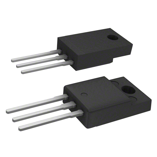
The MBRF20200CTH is a Schottky diode array manufactured by Taiwan Semiconductor Corporation, configured as 1 pair common cathode with 200V reverse voltage rating and 20A average rectified current per diode. The device is packaged in TO-220-3 Full Pack with isolated tab for through-hole mounting applications. This part is discontinued at DiGi Electronics, necessitating identification of equivalent and substitute components that maintain functional compatibility within specified electrical and mechanical parameters.
Substiute Parts
Key Parameters
| Parameter | Value |
|---|---|
| Diode Configuration | 1 Pair Common Cathode |
| Technology | Schottky |
| Voltage - DC Reverse (Vr) (Max) | 200 V |
| Current - Average Rectified (Io) (per Diode) | 20 A |
| Voltage - Forward (Vf) (Max) @ If | 1.05 V @ 20 A |
| Speed | Fast Recovery ≤ 500ns, > 200mA (Io) |
| Current - Reverse Leakage @ Vr | 100 µA @ 200 V |
| Operating Temperature - Junction | -55°C ~ 150°C |
| Mounting Type | Through Hole |
| Package / Case | TO-220-3 Full Pack, Isolated Tab |
| Supplier Device Package | ITO-220AB |
| RoHS Status | ROHS3 Compliant |
| Grade | Automotive |
| Qualification | AEC-Q101 |
Substitute Part Grouping Explanation
Substitution of the MBRF20200CTH is determined by the following critical parameters: diode configuration (1 pair common cathode), technology (Schottky), reverse voltage rating (200V), package type (TO-220-3 Full Pack, Isolated Tab), and mounting method (through hole). The average rectified current per diode is the primary differentiator among available substitutes, with acceptable alternatives ranging from 5A to 20A depending on application requirements.
Parametric equivalents maintain identical electrical specifications and package configuration. Similar substitutes share the same reverse voltage, package, and mounting characteristics but differ in current rating, forward voltage characteristics, or temperature range. All substitute parts listed comply with ROHS3 and maintain the same supplier device package designation (ITO-220AB).
Parameter Comparison
| Parameter | MBRF20200CTH | MBRF20200CT | VF20200C-E3/4W | VF20200G-E3/4W | VF30200C-E3/4W | VFT10200C-E3/4W |
|---|---|---|---|---|---|---|
| Manufacturer | Taiwan Semiconductor Corporation | Good-Ark Semiconductor | Vishay General Semiconductor - Diodes Division | Vishay General Semiconductor - Diodes Division | Vishay General Semiconductor - Diodes Division | Vishay General Semiconductor - Diodes Division |
| Diode Configuration | 1 Pair Common Cathode | 1 Pair Common Cathode | 1 Pair Common Cathode | 1 Pair Common Cathode | 1 Pair Common Cathode | 1 Pair Common Cathode |
| Technology | Schottky | Schottky | Schottky | Schottky | Schottky | Schottky |
| Voltage - DC Reverse (Vr) (Max) | 200 V | 200 V | 200 V | 200 V | 200 V | 200 V |
| Current - Average Rectified (Io) (per Diode) | 20 A | 10 A | 10 A | 10 A | 15 A | 5 A |
| Voltage - Forward (Vf) (Max) @ If | 1.05 V @ 20 A | Not Specified | 1.6 V @ 10 A | 1.7 V @ 10 A | 1.1 V @ 15 A | 1.6 V @ 5 A |
| Speed | Fast Recovery ≤ 500ns, > 200mA (Io) | Small Signal ≤ 200mA (Io), Any Speed | Fast Recovery ≤ 500ns, > 200mA (Io) | Fast Recovery ≤ 500ns, > 200mA (Io) | Fast Recovery ≤ 500ns, > 200mA (Io) | Fast Recovery ≤ 500ns, > 200mA (Io) |
| Current - Reverse Leakage @ Vr | 100 µA @ 200 V | 200 nA @ 200 V | 150 µA @ 200 V | 150 µA @ 200 V | 160 µA @ 200 V | 150 µA @ 200 V |
| Operating Temperature - Junction | -55°C ~ 150°C | Not Specified | -40°C ~ 150°C | -40°C ~ 150°C | -40°C ~ 150°C | -40°C ~ 150°C |
| Mounting Type | Through Hole | Through Hole | Through Hole | Through Hole | Through Hole | Through Hole |
| Package / Case | TO-220-3 Full Pack, Isolated Tab | TO-220-3 Full Pack, Isolated Tab | TO-220-3 Full Pack, Isolated Tab | TO-220-3 Full Pack, Isolated Tab | TO-220-3 Full Pack, Isolated Tab | TO-220-3 Full Pack, Isolated Tab |
| Supplier Device Package | ITO-220AB | ITO-220AB | ITO-220AB | ITO-220AB | ITO-220AB | ITO-220AB |
| RoHS Status | ROHS3 Compliant | ROHS3 Compliant | ROHS3 Compliant | ROHS3 Compliant | ROHS3 Compliant | ROHS3 Compliant |
| Product Status | Discontinued at DiGi Electronics | Active | Active | Active | Active | Active |
Engineering Selection Recommendations
MBRF20200CT (Good-Ark Semiconductor): This part is a parametric equivalent with identical 200V reverse voltage and TO-220-3 package configuration. However, the current rating is reduced to 10A per diode, and speed classification differs (small signal vs. fast recovery). This substitute is suitable only for applications where the 20A current requirement can be reduced to 10A. Product status is active with 22,800 units in stock.
VF20200C-E3/4W (Vishay TMBS® Series): This substitute maintains 200V reverse voltage and TO-220-3 package with 10A current rating. Forward voltage is specified at 1.6V @ 10A, higher than the original 1.05V @ 20A. Operating temperature range is -40°C to 150°C, narrower than the original -55°C to 150°C. Fast recovery speed characteristic is maintained. Product status is active with 17,311 units in stock.
VF20200G-E3/4W (Vishay TMBS® Series): This substitute shares identical package and voltage specifications with VF20200C-E3/4W but exhibits higher forward voltage at 1.7V @ 10A. Current rating is 10A per diode. Operating temperature range is -40°C to 150°C. Product status is active with 906 units in stock.
VF30200C-E3/4W (Vishay TMBS® Series): This substitute provides the closest current rating match at 15A per diode while maintaining 200V reverse voltage and TO-220-3 package. Forward voltage is 1.1V @ 15A, approaching the original specification. Operating temperature range is -40°C to 150°C. Fast recovery speed is maintained. Product status is active with 2,174 units in stock.
VFT10200C-E3/4W (Vishay TMBS® Series): This substitute is rated for 5A per diode, representing the lowest current option. All other electrical and package parameters align with the substitute group. Forward voltage is 1.6V @ 5A. Operating temperature range is -40°C to 150°C. Product status is active with 9,508 units in stock.
All substitute parts maintain ROHS3 compliance and identical package designation (ITO-220AB). Selection should be based on application current requirements and acceptable forward voltage characteristics at the specified operating current.
Frequently Asked Questions (FAQ)
Q: Can MBRF20200CT directly replace MBRF20200CTH in all applications?
A: MBRF20200CT shares the same 200V reverse voltage rating and TO-220-3 package configuration. However, the current rating is reduced from 20A to 10A per diode. Direct replacement is only suitable for applications where the maximum required current does not exceed 10A per diode. Speed classification also differs (small signal vs. fast recovery), which may affect switching performance in high-frequency applications.
Q: What is the primary difference between the Vishay TMBS® series substitutes?
A: The Vishay TMBS® series substitutes (VF20200C-E3/4W, VF20200G-E3/4W, VF30200C-E3/4W, and VFT10200C-E3/4W) all maintain 200V reverse voltage and TO-220-3 package configuration. The primary differences are current rating (5A, 10A, or 15A per diode) and forward voltage characteristics at their respective rated currents. All maintain fast recovery speed and -40°C to 150°C operating temperature range.
Q: Is the operating temperature range difference significant between MBRF20200CTH and substitute parts?
A: The original MBRF20200CTH operates from -55°C to 150°C, while most substitute parts operate from -40°C to 150°C. The lower temperature limit difference of 15°C is significant only for applications requiring operation below -40°C. For standard industrial and automotive applications operating above -40°C, this difference is not a limiting factor.
Q: Which substitute part provides the best forward voltage match to the original MBRF20200CTH?
A: VF30200C-E3/4W provides the closest forward voltage characteristic at 1.1V @ 15A, compared to the original 1.05V @ 20A. This part also offers the highest current rating among substitutes at 15A per diode, making it suitable for applications requiring current levels between 10A and 20A.
Q: Are all substitute parts automotive-grade like the original MBRF20200CTH?
A: The original MBRF20200CTH carries automotive grade designation with AEC-Q101 qualification. The provided substitute part specifications do not explicitly state automotive grade or AEC-Q101 qualification. Verification of automotive compliance requirements should be confirmed with the respective manufacturers before selection for automotive applications.
Q: Can multiple lower-rated diodes be paralleled to achieve the original 20A rating?
A: The provided specifications do not include information regarding parallel operation or current sharing characteristics. Parallel connection of diodes requires specific design considerations and manufacturer guidance. This approach is outside the scope of direct substitution and requires separate engineering analysis.
Q: What is the significance of the "Isolated Tab" designation in the package specification?
A: The "Isolated Tab" designation indicates that the tab of the TO-220-3 package is electrically isolated from the diode cathode. This allows the tab to be mounted directly to a heat sink without requiring electrical isolation. All substitute parts maintain this isolated tab configuration, ensuring mechanical compatibility with existing thermal management designs.
Q: How does reverse leakage current affect substitute selection?
A: The original MBRF20200CTH specifies 100µA reverse leakage @ 200V. Substitute parts range from 200nA (MBRF20200CT) to 160µA (VF30200C-E3/4W). Lower reverse leakage reduces standby power dissipation and heat generation. Higher reverse leakage increases power loss in standby conditions. Selection should consider the application's standby power budget and thermal constraints.
Alternative Parts

SJ6012L2TP
Littelfuse Inc.
6 Alternative Parts

JMK107BBJ476MA-RE
Taiyo Yuden
10 Alternative Parts

GMK107BBJ475MA-T
Taiyo Yuden
5 Alternative Parts
SJ6020N2ARP
Littelfuse Inc.
3 Alternative Parts
SJ6025R2ATP
Littelfuse Inc.
4 Alternative Parts

2474-05L
API Delevan Inc.
1 Alternative Parts

4590R-684K
API Delevan Inc.
1 Alternative Parts

CM6560R-334
API Delevan Inc.
1 Alternative Parts

CM6460-104
API Delevan Inc.
1 Alternative Parts

5526-12
API Delevan Inc.
1 Alternative Parts