


Request Quote
(Ships tomorrow)
MBRF10200CT-JT Equivalent & Substitute Parts
Part Overview
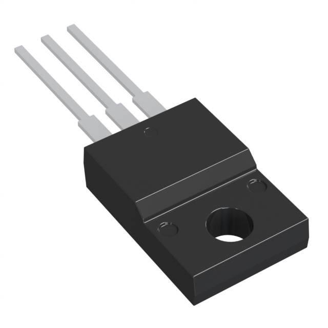
The MBRF10200CT-JT is a Schottky diode array manufactured by Diodes Incorporated, configured as 1 pair common cathode with 200 V reverse voltage rating and 5 A average rectified current per diode. The device is packaged in TO-220-3 with isolated tab (ITO-220AB) for through-hole mounting applications. This part is classified as obsolete, necessitating identification of active equivalent and substitute components for new designs and ongoing production requirements.
Substiute Parts
Key Parameters
| Parameter | Value |
|---|---|
| Diode Configuration | 1 Pair Common Cathode |
| Technology | Schottky |
| Voltage - DC Reverse (Vr) (Max) | 200 V |
| Current - Average Rectified (Io) (per Diode) | 5 A |
| Voltage - Forward (Vf) (Max) @ If | 910 mV @ 5 A |
| Speed | Fast Recovery ≤ 500ns, > 200mA (Io) |
| Current - Reverse Leakage @ Vr | 100 µA @ 200 V |
| Operating Temperature - Junction | -55°C ~ 175°C |
| Mounting Type | Through Hole |
| Package / Case | TO-220-3 Full Pack, Isolated Tab |
| RoHS Status | ROHS3 Compliant |
| Moisture Sensitivity Level (MSL) | 1 (Unlimited) |
Substitute Part Grouping Explanation
Substitution of the MBRF10200CT-JT is determined by strict equivalence across the following critical parameters:
Core Electrical Parameters:
- Voltage - DC Reverse (Vr) (Max): 200 V
- Current - Average Rectified (Io) (per Diode): 5 A
- Diode Configuration: 1 Pair Common Cathode
- Technology: Schottky
- Speed: Fast Recovery ≤ 500ns, > 200mA (Io)
Mechanical Parameters:
- Mounting Type: Through Hole
- Package / Case: TO-220-3 Full Pack
Compliance Parameters:
- RoHS Status: ROHS3 Compliant
- Moisture Sensitivity Level (MSL): 1 (Unlimited)
Substitute parts are grouped into two categories based on product status and package configuration:
MFR Recommended Substitutes: Parts with active product status and full electrical parameter compatibility.
Parametric Equivalents: Parts with parametric compatibility but non-active product status, suitable for legacy system support or inventory management.
Parameter Comparison
| Parameter | MBRF10200CT-JT | MBR10200CTF-G1 | DSTF10200C | TSF10H200C |
|---|---|---|---|---|
| Manufacturer | Diodes Incorporated | Diodes Incorporated | Littelfuse Inc. | Taiwan Semiconductor Corporation |
| Product Status | Obsolete | Active | Active | Not For New Designs |
| Diode Configuration | 1 Pair Common Cathode | 1 Pair Common Cathode | 1 Pair Common Cathode | 1 Pair Common Cathode |
| Technology | Schottky | Schottky | Schottky | Schottky |
| Voltage - DC Reverse (Vr) (Max) | 200 V | 200 V | 200 V | 200 V |
| Current - Average Rectified (Io) (per Diode) | 5 A | 5 A | 5 A | 5 A |
| Voltage - Forward (Vf) (Max) @ If | 910 mV @ 5 A | 950 mV @ 5 A | 900 mV @ 5 A | 910 mV @ 5 A |
| Speed | Fast Recovery ≤ 500ns, > 200mA (Io) | Fast Recovery ≤ 500ns, > 200mA (Io) | Fast Recovery ≤ 500ns, > 200mA (Io) | Fast Recovery ≤ 500ns, > 200mA (Io) |
| Current - Reverse Leakage @ Vr | 100 µA @ 200 V | 150 µA @ 200 V | 10 µA @ 200 V | 100 µA @ 200 V |
| Operating Temperature - Junction | -55°C ~ 175°C | 150°C (Max) | -55°C ~ 150°C | -55°C ~ 150°C |
| Mounting Type | Through Hole | Through Hole | Through Hole | Through Hole |
| Package / Case | TO-220-3 Full Pack, Isolated Tab | TO-220-3 Full Pack | TO-220-3 Full Pack, Isolated Tab | TO-220-3 Full Pack, Isolated Tab |
| Supplier Device Package | ITO-220AB | TO-220F-3 | ITO-220AB | ITO-220AB |
| RoHS Status | ROHS3 Compliant | ROHS3 Compliant | ROHS3 Compliant | ROHS3 Compliant |
| Moisture Sensitivity Level (MSL) | 1 (Unlimited) | 1 (Unlimited) | 1 (Unlimited) | 1 (Unlimited) |
| REACH Status | REACH Affected | REACH Unaffected | REACH Unaffected | REACH Unaffected |
Engineering Selection Recommendations
For New Designs:
MBR10200CTF-G1 (Diodes Incorporated) is the primary recommended substitute. This part maintains active product status, full ROHS3 compliance, and REACH unaffected status. The forward voltage specification of 950 mV @ 5 A represents a 40 mV increase over the original part, which is within acceptable tolerance for most rectification applications. The maximum junction temperature specification of 150°C is lower than the original 175°C; thermal design review is required for applications operating above 150°C.
DSTF10200C (Littelfuse Inc.) is an alternative active substitute with identical package configuration (ITO-220AB). This part exhibits superior reverse leakage characteristics at 10 µA @ 200 V compared to the original 100 µA, and forward voltage of 900 mV @ 5 A is closer to the original specification. Maximum junction temperature is 150°C. REACH unaffected status provides regulatory advantage.
For Legacy System Support:
TSF10H200C (Taiwan Semiconductor Corporation) provides parametric equivalence with identical electrical characteristics to the original part. Product status is classified as "Not For New Designs," limiting application to existing production runs or field replacements where design re-qualification is not feasible. This part maintains the original operating temperature range of -55°C ~ 150°C and identical forward voltage specification of 910 mV @ 5 A.
Package Consideration:
MBR10200CTF-G1 uses TO-220F-3 package (non-isolated tab) versus the original ITO-220AB (isolated tab). PCB layout and thermal management design must accommodate this package difference. DSTF10200C and TSF10H200C maintain the isolated tab configuration, requiring no layout modification.
Frequently Asked Questions (FAQ)
Q: Can MBR10200CTF-G1 be used as a direct replacement for MBRF10200CT-JT?
A: MBR10200CTF-G1 is electrically compatible across all critical parameters: 200 V reverse voltage, 5 A average rectified current, Schottky technology, and fast recovery speed. However, the package differs (TO-220F-3 non-isolated tab versus ITO-220AB isolated tab). PCB layout must be re-evaluated to accommodate the non-isolated tab configuration. Forward voltage increases from 910 mV to 950 mV, which is acceptable for most rectification circuits. Maximum junction temperature is 150°C versus the original 175°C.
Q: What is the difference between DSTF10200C and TSF10H200C?
A: Both parts are parametric equivalents with identical electrical specifications to the original MBRF10200CT-JT. DSTF10200C (Littelfuse) has active product status and superior reverse leakage performance (10 µA @ 200 V). TSF10H200C (Taiwan Semiconductor Corporation) is classified as "Not For New Designs" and exhibits reverse leakage of 100 µA @ 200 V, matching the original part. Both maintain the ITO-220AB isolated tab package.
Q: Are all substitute parts ROHS3 compliant?
A: Yes. All substitute parts listed (MBR10200CTF-G1, DSTF10200C, TSF10H200C) are ROHS3 compliant with Moisture Sensitivity Level 1 (Unlimited), matching the original part's compliance status.
Q: What is the significance of REACH status differences?
A: The original MBRF10200CT-JT is REACH Affected, while all substitute parts are REACH Unaffected. For applications subject to REACH regulations, the substitute parts provide regulatory advantage and eliminate potential supply chain restrictions associated with REACH-affected components.
Q: Which substitute part has the lowest reverse leakage current?
A: DSTF10200C exhibits the lowest reverse leakage at 10 µA @ 200 V, compared to 100 µA @ 200 V for both MBRF10200CT-JT and TSF10H200C, and 150 µA @ 200 V for MBR10200CTF-G1. Lower reverse leakage reduces standby power dissipation in applications with sustained reverse bias conditions.
Q: Can TSF10H200C be used in new product designs?
A: TSF10H200C is classified as "Not For New Designs." This designation indicates the manufacturer does not recommend this part for new design implementations. Use is limited to legacy system support, field replacements, or existing production continuity where design re-qualification is not feasible.
Q: What is the impact of the 40 mV forward voltage increase in MBR10200CTF-G1?
A: Forward voltage increases from 910 mV to 950 mV @ 5 A. This 40 mV increase results in approximately 200 mW additional power dissipation per diode at 5 A continuous current. Thermal design review is required for high-current applications or designs with limited thermal margin. For most rectification circuits operating below maximum current ratings, this increase is within acceptable tolerance.
Q: Are all substitute parts available in the same packaging format?
A: MBR10200CTF-G1 uses TO-220F-3 (non-isolated tab), while DSTF10200C and TSF10H200C use ITO-220AB (isolated tab). The original MBRF10200CT-JT uses ITO-220AB. If isolated tab configuration is required for thermal or electrical isolation, DSTF10200C or TSF10H200C are appropriate selections. If non-isolated tab is acceptable, MBR10200CTF-G1 is suitable.
Alternative Parts

SJ6012L2TP
Littelfuse Inc.
6 Alternative Parts

JMK107BBJ476MA-RE
Taiyo Yuden
10 Alternative Parts

GMK107BBJ475MA-T
Taiyo Yuden
5 Alternative Parts
SJ6020N2ARP
Littelfuse Inc.
3 Alternative Parts
SJ6025R2ATP
Littelfuse Inc.
4 Alternative Parts

2474-05L
API Delevan Inc.
1 Alternative Parts

4590R-684K
API Delevan Inc.
1 Alternative Parts

CM6560R-334
API Delevan Inc.
1 Alternative Parts

CM6460-104
API Delevan Inc.
1 Alternative Parts

5526-12
API Delevan Inc.
1 Alternative Parts