


Request Quote
(Ships tomorrow)
MAX5014CSA-T Equivalent & Substitute Parts
Part Overview
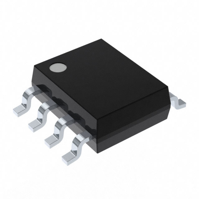
The MAX5014CSA-T is a Flyback Regulator Controller IC manufactured by Analog Devices Inc./Maxim Integrated, designed for positive, isolation-capable output step-up/step-down DC-DC conversion applications. This device operates as a transistor driver with a single output phase and is packaged in 8-SOIC surface mount configuration.
The MAX5014CSA-T is classified as obsolete. Identifying suitable substitute components is necessary to maintain design continuity, ensure supply chain availability, and support ongoing production requirements for systems utilizing this controller topology.
Substiute Parts
Key Parameters
| Parameter | MAX5014CSA-T |
|---|---|
| Manufacturer | Analog Devices Inc./Maxim Integrated |
| Category | Power Management (PMIC) |
| Description | IC REG CTRLR FLYBACK 8SOIC |
| Topology | Flyback |
| Output Type | Transistor Driver |
| Function | Step-Up/Step-Down |
| Output Configuration | Positive, Isolation Capable |
| Number of Outputs | 1 |
| Voltage - Supply (Vcc/Vdd) | 13V ~ 36V |
| Frequency - Switching | 275kHz |
| Duty Cycle (Max) | 85% |
| Operating Temperature | 0°C ~ 70°C (TA) |
| Package / Case | 8-SOIC (0.154", 3.90mm Width) |
| Product Status | Obsolete |
| RoHS Status | ROHS3 Compliant |
| Moisture Sensitivity Level (MSL) | 1 (Unlimited) |
Substitute Part Grouping Explanation
Substitution of the MAX5014CSA-T is evaluated based on the following critical parameters that define functional equivalence:
Topology & Output Configuration: The substitute must support positive, isolation-capable output configuration with transistor driver output type.
Supply Voltage Range: The substitute must operate within or encompass the 13V ~ 36V supply voltage specification of the original part.
Switching Frequency & Duty Cycle: The substitute must support the operational frequency and maximum duty cycle requirements of the application.
Output Function: The substitute must provide step-up/step-down DC-DC conversion capability.
Compliance & Availability: The substitute must maintain ROHS3 compliance and demonstrate active product status with confirmed inventory availability.
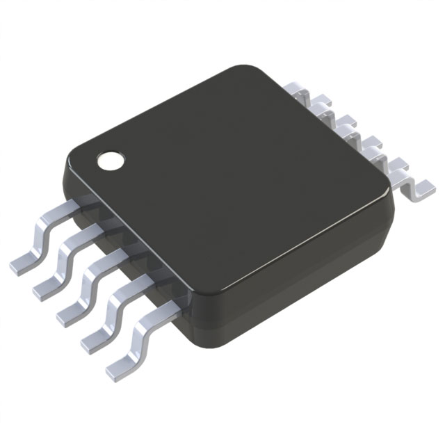
The MAX17499BAUB+T qualifies as a manufacturer-recommended substitute based on these criteria, despite differences in package type and extended operating temperature range.
Parameter Comparison
| Parameter | MAX5014CSA-T | MAX17499BAUB+T |
|---|---|---|
| Manufacturer | Analog Devices Inc./Maxim Integrated | Analog Devices Inc./Maxim Integrated |
| Category | Power Management (PMIC) | Power Management (PMIC) |
| Output Type | Transistor Driver | Transistor Driver |
| Output Configuration | Positive, Isolation Capable | Positive, Isolation Capable |
| Number of Outputs | 1 | 1 |
| Output Phases | 1 | 1 |
| Voltage - Supply (Vcc/Vdd) | 13V ~ 36V | 9.5V ~ 24V |
| Frequency - Switching | 275kHz | 50kHz ~ 2.5MHz |
| Duty Cycle (Max) | 85% | 75% |
| Synchronous Rectifier | No | No |
| Clock Sync | No | No |
| Operating Temperature | 0°C ~ 70°C (TA) | -40°C ~ 125°C (TJ) |
| Mounting Type | Surface Mount | Surface Mount |
| Package / Case | 8-SOIC (0.154", 3.90mm Width) | 10-TFSOP, 10-MSOP (0.118", 3.00mm Width) |
| Product Status | Obsolete | Active |
| RoHS Status | ROHS3 Compliant | ROHS3 Compliant |
| Moisture Sensitivity Level (MSL) | 1 (Unlimited) | 1 (Unlimited) |
Engineering Selection Recommendations
The MAX17499BAUB+T is designated as the manufacturer-recommended substitute for the obsolete MAX5014CSA-T. Both devices maintain ROHS3 compliance and unlimited moisture sensitivity classification, ensuring regulatory and environmental consistency.
The MAX17499BAUB+T offers active product status with confirmed inventory availability (1140 pcs), providing supply chain continuity for applications requiring Flyback controller functionality. The extended operating temperature range (-40°C ~ 125°C junction temperature) of the substitute provides enhanced thermal performance compared to the original part specification (0°C ~ 70°C ambient).
Design integration requires evaluation of the following parameter differences:
Supply voltage range of the substitute (9.5V ~ 24V) is narrower than the original (13V ~ 36V). Applications operating above 24V require design verification.
Maximum duty cycle of the substitute (75%) is lower than the original (85%). Applications requiring higher duty cycle operation must be reassessed.
Package transition from 8-SOIC to 10-TFSOP/10-MSOP requires PCB layout modification and schematic redesign.
Switching frequency range of the substitute (50kHz ~ 2.5MHz) encompasses the original fixed frequency (275kHz), supporting frequency-compatible operation.
Frequently Asked Questions (FAQ)
Q: Can the MAX17499BAUB+T directly replace the MAX5014CSA-T without circuit modification?
A: No. While both devices provide transistor driver output with positive, isolation-capable configuration, the package change from 8-SOIC to 10-TFSOP/10-MSOP requires PCB layout redesign. Additionally, the narrower supply voltage range (9.5V ~ 24V vs. 13V ~ 36V) and lower maximum duty cycle (75% vs. 85%) must be verified against application requirements.
Q: What is the primary reason for substitution?
A: The MAX5014CSA-T is classified as obsolete. The MAX17499BAUB+T is the manufacturer-recommended active substitute with confirmed inventory availability.
Q: Are there compliance differences between the two parts?
A: Both parts maintain ROHS3 compliance and MSL 1 (Unlimited) classification. No compliance degradation occurs with substitution.
Q: Does the substitute support the same switching frequency?
A: The MAX17499BAUB+T supports a programmable switching frequency range of 50kHz ~ 2.5MHz, which encompasses the original fixed frequency of 275kHz. Frequency-compatible operation is supported within this range.
Q: What are the thermal operating differences?
A: The original part specifies 0°C ~ 70°C ambient temperature operation. The substitute specifies -40°C ~ 125°C junction temperature operation, providing extended thermal capability suitable for wider environmental conditions.
Q: Is the supply voltage range compatible with existing designs?
A: The substitute supply voltage range (9.5V ~ 24V) is narrower than the original (13V ~ 36V). Applications operating at supply voltages above 24V are not compatible with the substitute and require alternative solutions.
Alternative Parts

SJ6012L2TP
Littelfuse Inc.
6 Alternative Parts

JMK107BBJ476MA-RE
Taiyo Yuden
10 Alternative Parts

GMK107BBJ475MA-T
Taiyo Yuden
5 Alternative Parts
SJ6020N2ARP
Littelfuse Inc.
3 Alternative Parts
SJ6025R2ATP
Littelfuse Inc.
4 Alternative Parts

2474-05L
API Delevan Inc.
1 Alternative Parts

4590R-684K
API Delevan Inc.
1 Alternative Parts

CM6560R-334
API Delevan Inc.
1 Alternative Parts

CM6460-104
API Delevan Inc.
1 Alternative Parts

5526-12
API Delevan Inc.
1 Alternative Parts