


Request Quote
(Ships tomorrow)
MAX4052C/D Equivalent & Substitute Parts
Part Overview
The MAX4052C/D is a 2-circuit IC switch with SP4T (Single Pole, 4-Throw) configuration and 100Ohm on-state resistance, manufactured by Analog Devices Inc./Maxim Integrated. This die-packaged component is classified as an Interface category switch for multiplexing and demultiplexing applications. The product is currently obsolete, making identification of compatible substitute parts essential for ongoing system support and procurement planning.
Substiute Parts
Key Parameters
| Parameter | Value |
|---|---|
| Switch Circuit Configuration | SP4T |
| Multiplexer/Demultiplexer Circuit | 4:1 |
| Number of Circuits | 2 |
| On-State Resistance (Max) | 100Ohm |
| Channel-to-Channel Matching (ΔRon) | 12Ohm (Max) |
| Voltage - Supply, Single (V+) | 2V ~ 16V |
| Voltage - Supply, Dual (V±) | ±2.7V ~ 8V |
| Switch Time (Ton, Toff) (Max) | 175ns, 150ns |
| Charge Injection | 2pC |
| Channel Capacitance (CS(off), CD(off)) | 2pF, 2pF |
| Current - Leakage (IS(off)) (Max) | 1nA |
| Crosstalk | -90dB @ 100kHz |
| Operating Temperature | 0°C ~ 70°C |
| RoHS Status | ROHS3 Compliant |
| Moisture Sensitivity Level (MSL) | 1 (Unlimited) |
Substitute Part Grouping Explanation
Substitution eligibility for the MAX4052C/D is determined by strict equivalence across the following critical parameters:
- Switch Architecture: SP4T configuration with 4:1 multiplexer/demultiplexer circuit and 2 independent circuits
- Electrical Performance: On-state resistance of 100Ohm maximum with 12Ohm maximum channel-to-channel matching
- Supply Voltage Compatibility: Single supply range 2V ~ 16V and dual supply range ±2.7V ~ 8V
- Switching Characteristics: Maximum switch times of 175ns (Ton) and 150ns (Toff)
- Signal Integrity Parameters: Charge injection of 2pC, channel capacitance of 2pF, leakage current of 1nA maximum, and crosstalk of -90dB @ 100kHz
- Environmental Specifications: Operating temperature range 0°C ~ 70°C, ROHS3 compliance, and MSL 1 rating
The primary difference between the main part and substitute is packaging format: the MAX4052C/D is supplied as a die, while substitute parts may be available in standard surface-mount packages. Functional and electrical parameters remain identical across all qualified substitutes.
Parameter Comparison
| Parameter | MAX4052C/D (Die) | MAX4052CSE+ (16-SOIC) |
|---|---|---|
| Switch Circuit | SP4T | SP4T |
| Multiplexer/Demultiplexer Circuit | 4:1 | 4:1 |
| Number of Circuits | 2 | 2 |
| On-State Resistance (Max) | 100Ohm | 100Ohm |
| Channel-to-Channel Matching (ΔRon) | 12Ohm (Max) | 12Ohm (Max) |
| Voltage - Supply, Single (V+) | 2V ~ 16V | 2V ~ 16V |
| Voltage - Supply, Dual (V±) | ±2.7V ~ 8V | ±2.7V ~ 8V |
| Switch Time (Ton, Toff) (Max) | 175ns, 150ns | 175ns, 150ns |
| Charge Injection | 2pC | 2pC |
| Channel Capacitance (CS(off), CD(off)) | 2pF, 2pF | 2pF, 2pF |
| Current - Leakage (IS(off)) (Max) | 1nA | 1nA |
| Crosstalk | -90dB @ 100kHz | -90dB @ 100kHz |
| Operating Temperature | 0°C ~ 70°C | 0°C ~ 70°C |
| Product Status | Obsolete | Active |
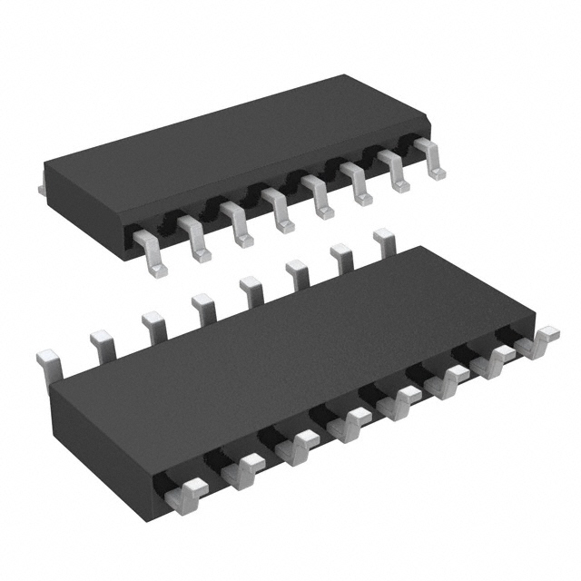
| Packaging | Die | 16-SOIC (0.154", 3.90mm Width) |
| RoHS Status | ROHS3 Compliant | ROHS3 Compliant |
| MSL Rating | 1 (Unlimited) | 1 (Unlimited) |
Engineering Selection Recommendations
The MAX4052CSE+ in 16-SOIC packaging is the qualified substitute for the obsolete MAX4052C/D die. Both parts maintain identical electrical and functional specifications across all critical parameters. The MAX4052CSE+ is currently in active production status with established supply availability, making it the appropriate selection for new designs and ongoing system support.
Both parts carry ROHS3 compliance and MSL 1 ratings, ensuring compatibility with standard manufacturing and storage protocols. The transition from die to 16-SOIC package format requires only standard PCB layout and assembly adjustments with no impact on circuit performance or electrical characteristics.
Frequently Asked Questions (FAQ)
Q: Can MAX4052CSE+ directly replace MAX4052C/D in all applications?
A: Electrically and functionally, yes. The MAX4052CSE+ maintains identical specifications for switch configuration, on-state resistance, supply voltage ranges, switching times, and signal integrity parameters. The primary consideration is packaging format: the MAX4052C/D is a die requiring hybrid assembly, while the MAX4052CSE+ is a 16-SOIC surface-mount package suitable for standard PCB assembly.
Q: What are the key parameters that define substitution eligibility?
A: Substitution is based on strict equivalence in switch circuit configuration (SP4T), multiplexer circuit type (4:1), number of circuits (2), on-state resistance (100Ohm maximum), channel matching (12Ohm maximum), supply voltage ranges (2V ~ 16V single, ±2.7V ~ 8V dual), switching times (175ns/150ns), charge injection (2pC), channel capacitance (2pF), leakage current (1nA), and crosstalk performance (-90dB @ 100kHz).
Q: Why is the MAX4052C/D obsolete?
A: The MAX4052C/D die format has been superseded by the MAX4052CSE+ in standard 16-SOIC packaging, which offers improved availability and simplified integration into modern PCB assembly processes.
Q: Are there any compliance differences between the parts?
A: No. Both the MAX4052C/D and MAX4052CSE+ are ROHS3 compliant with MSL 1 ratings and identical environmental specifications.
Q: What packaging considerations apply when transitioning from die to 16-SOIC?
A: The 16-SOIC package (0.154" width, 3.90mm) requires standard surface-mount assembly and PCB layout. No circuit design changes are necessary, as all electrical parameters remain identical.
Alternative Parts

SJ6012L2TP
Littelfuse Inc.
6 Alternative Parts

JMK107BBJ476MA-RE
Taiyo Yuden
10 Alternative Parts

GMK107BBJ475MA-T
Taiyo Yuden
5 Alternative Parts
SJ6020N2ARP
Littelfuse Inc.
3 Alternative Parts
SJ6025R2ATP
Littelfuse Inc.
4 Alternative Parts

2474-05L
API Delevan Inc.
1 Alternative Parts

4590R-684K
API Delevan Inc.
1 Alternative Parts

CM6560R-334
API Delevan Inc.
1 Alternative Parts

CM6460-104
API Delevan Inc.
1 Alternative Parts

5526-12
API Delevan Inc.
1 Alternative Parts