


Request Quote
(Ships tomorrow)
LT1079MJ Equivalent & Substitute Parts
Part Overview
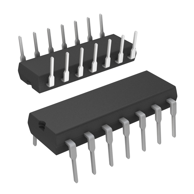
The LT1079MJ is a general-purpose operational amplifier featuring four independent circuits in a 14-CERDIP package. Manufactured by Analog Devices Inc., this device operates across a wide supply voltage range of 2.2V to 30V and is rated for industrial temperature applications from -55°C to 125°C. The LT1079MJ is classified as an obsolete product, necessitating identification of active equivalent alternatives for new designs and ongoing production requirements. Substitute parts must maintain functional compatibility while meeting current manufacturing and compliance standards.
Substiute Parts
Key Parameters
| Parameter | LT1079MJ |
|---|---|
| Amplifier Type | General Purpose |
| Number of Circuits | 4 |
| Slew Rate | 0.1 V/µs |
| Gain Bandwidth Product | 200 kHz |
| Current - Input Bias | 6 nA |
| Voltage - Input Offset | 60 µV |
| Current - Supply | 39 µA (x4 Channels) |
| Voltage - Supply Span (Min) | 2.2 V |
| Voltage - Supply Span (Max) | 30 V |
| Operating Temperature | -55°C ~ 125°C |
| Mounting Type | Through Hole |
| Package / Case | 14-CDIP (0.300", 7.62mm) |
| Product Status | Obsolete |
| Moisture Sensitivity Level | 1 (Unlimited) |
Substitute Part Grouping Explanation
Substitution of the LT1079MJ is determined by the following critical parameters:
Functional Equivalence Criteria:
- Four independent operational amplifier circuits
- Gain bandwidth product of 200 kHz
- General-purpose amplifier classification
- Through-hole mounting compatibility with 14-pin DIP package footprint
Electrical Operating Range:
- Supply voltage compatibility within specified minimum and maximum ranges
- Input bias current and input offset voltage characteristics suitable for general-purpose applications
- Operating temperature range sufficient for intended application environment
Physical and Manufacturing Compatibility:
- 14-pin DIP package format with 0.300" (7.62mm) pitch
- Moisture sensitivity level MSL 1 classification
- Compliance with applicable trade regulations (ECCN EAR99, HTSUS 8542.33.0001)
The LT1491AIN#PBF qualifies as a functional substitute based on matching the four-circuit configuration, 200 kHz gain bandwidth product, and compatible 14-pin DIP package footprint. Both devices share identical package pitch and through-hole mounting characteristics, enabling direct board-level substitution.
Parameter Comparison
| Parameter | LT1079MJ | LT1491AIN#PBF | Compatibility Notes |
|---|---|---|---|
| Amplifier Type | General Purpose | General Purpose | Functionally equivalent |
| Number of Circuits | 4 | 4 | Identical circuit count |
| Slew Rate | 0.1 V/µs | 0.06 V/µs | Substitute has lower slew rate |
| Gain Bandwidth Product | 200 kHz | 200 kHz | Identical bandwidth |
| Current - Input Bias | 6 nA | 1 nA | Substitute has lower input bias current |
| Voltage - Input Offset | 60 µV | 285 µV | Substitute has higher input offset voltage |
| Current - Supply | 39 µA (x4 Channels) | 50 µA (x4 Channels) | Substitute has higher supply current |
| Voltage - Supply Span (Min) | 2.2 V | 2 V | Substitute operates at lower minimum voltage |
| Voltage - Supply Span (Max) | 30 V | 44 V | Substitute supports higher maximum voltage |
| Operating Temperature | -55°C ~ 125°C | -40°C ~ 85°C | Original has wider temperature range |
| Mounting Type | Through Hole | Through Hole | Identical mounting method |
| Package / Case | 14-CDIP (0.300", 7.62mm) | 14-DIP (0.300", 7.62mm) | Compatible footprint and pitch |
| Moisture Sensitivity Level | 1 (Unlimited) | 1 (Unlimited) | Identical MSL classification |
| Product Status | Obsolete | Active | Substitute is in active production |
Engineering Selection Recommendations
Product Status Consideration: The LT1079MJ is classified as obsolete, making the LT1491AIN#PBF the appropriate active alternative for new designs and production continuity. The substitute maintains active product status with Analog Devices Inc., ensuring ongoing availability and manufacturing support.
Compliance and Certifications: The LT1491AIN#PBF carries RoHS3 compliance and REACH unaffected status, meeting current environmental and regulatory requirements. Both devices share identical ECCN (EAR99) and HTSUS (8542.33.0001) classifications, maintaining consistent trade compliance profiles.
Electrical Parameter Differences: The LT1491AIN#PBF exhibits improved input bias current performance (1 nA versus 6 nA) and expanded supply voltage range (2V to 44V versus 2.2V to 30V). The substitute features rail-to-rail output capability, providing enhanced signal swing characteristics. These improvements represent functional enhancements rather than limitations.
The LT1491AIN#PBF demonstrates higher input offset voltage (285 µV versus 60 µV) and lower slew rate (0.06 V/µs versus 0.1 V/µs). Applications requiring the original device's precision offset voltage or high-speed transient response characteristics require detailed circuit analysis to confirm substitution suitability.
Temperature Range Limitation: The LT1491AIN#PBF operates across -40°C to 85°C, narrower than the LT1079MJ's -55°C to 125°C range. Applications requiring extended temperature operation below -40°C or above 85°C cannot use this substitute without alternative solutions.
Package and Mounting Compatibility: Both devices utilize identical 14-pin DIP packages with 0.300" (7.62mm) pitch and through-hole mounting, enabling direct board-level substitution without layout modifications.
Frequently Asked Questions (FAQ)
Q: Can the LT1491AIN#PBF directly replace the LT1079MJ in existing designs?
A: Direct substitution is possible from a physical and functional standpoint due to identical four-circuit configuration, 200 kHz gain bandwidth product, and compatible 14-pin DIP package footprint. However, circuit-level verification is required to confirm compatibility with application-specific electrical requirements, particularly regarding input offset voltage tolerance and operating temperature range.
Q: What are the key electrical differences between these devices?
A: The LT1491AIN#PBF provides lower input bias current (1 nA versus 6 nA), expanded supply voltage range (2V to 44V versus 2.2V to 30V), and rail-to-rail output capability. The substitute exhibits higher input offset voltage (285 µV versus 60 µV) and lower slew rate (0.06 V/µs versus 0.1 V/µs). Supply current consumption is also higher (50 µA versus 39 µA per four channels).
Q: Are there temperature range limitations with the substitute?
A: Yes. The LT1491AIN#PBF operates from -40°C to 85°C, compared to the LT1079MJ's -55°C to 125°C range. Applications requiring operation below -40°C or above 85°C cannot use this substitute.
Q: Do both devices share the same package footprint?
A: Yes. Both the LT1079MJ and LT1491AIN#PBF utilize 14-pin DIP packages with 0.300" (7.62mm) pitch, enabling direct board-level substitution without PCB layout modifications.
Q: What is the product status difference between these parts?
A: The LT1079MJ is classified as obsolete, while the LT1491AIN#PBF is an active product. The substitute ensures ongoing availability and manufacturing support for new designs and production continuity.
Q: Are there compliance differences between the two devices?
A: Both devices share identical ECCN (EAR99) and HTSUS (8542.33.0001) classifications. The LT1491AIN#PBF carries RoHS3 compliance and REACH unaffected status, meeting current environmental regulations.
Q: Which device should be selected for new designs?
A: The LT1491AIN#PBF should be selected for new designs due to its active product status, improved input bias current performance, expanded supply voltage range, and current environmental compliance certifications. Application-specific electrical requirements must be verified against the parameter comparison table.
Alternative Parts

SJ6012L2TP
Littelfuse Inc.
6 Alternative Parts

JMK107BBJ476MA-RE
Taiyo Yuden
10 Alternative Parts

GMK107BBJ475MA-T
Taiyo Yuden
5 Alternative Parts
SJ6020N2ARP
Littelfuse Inc.
3 Alternative Parts
SJ6025R2ATP
Littelfuse Inc.
4 Alternative Parts

2474-05L
API Delevan Inc.
1 Alternative Parts

4590R-684K
API Delevan Inc.
1 Alternative Parts

CM6560R-334
API Delevan Inc.
1 Alternative Parts

CM6460-104
API Delevan Inc.
1 Alternative Parts

5526-12
API Delevan Inc.
1 Alternative Parts